Andover Controls i2 810 Controller

File Preview
Click below to download for free
Click below to download for free
File Data
| Name | andover-controls-i2-810-controller-1394762508.pdf |
|---|---|
| Type | |
| Size | 797.26 KB |
| Downloads |
Text Preview
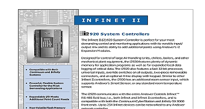
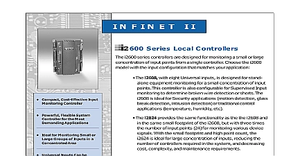
Powerful Flexible Local for the Most Applications Expandable I O Meets Point Count Needs Non Volatile Flash Memory Utmost Reliability Both Application and Operating Optional Display Keypad Easy Operator Mounted Local Extended Storage of Data View and Modify Information Optional Smart Sensor Local On Board Service Port N F I N E T I I 810 Series Local Controllers i2810 series controllers are designed for control of Air Handling Units Top Units and other mechanical plant equipment Choose the i2810 with the configuration that matches your application The i2810 designed for stand alone equipment control of Roof Units Air Handling Units or other packaged mechanical features eight Universal Inputs one Smart Sensor Sensor input plus eight program controlled Digital The i2814 designed for stand alone equipment control of Roof or Air Handling Units features eight Universal Inputs one Sensor Room Sensor input plus four program controlled Outputs and four Analog Outputs for direct control of requiring 0 10 volt control signals The i2814 is compatible with Continuum only models feature an additional room sensor input which supports Smart Sensor or any standard room temperature sensor The series also features universal inputs a real time clock override on all outputs two piece removeable connectors and the ability expand the I O for additional points i2810 series also features Flash memory increased user memory a fast 32 bit processor for faster scan times with plenty of memory for data logging of your critical data i2810 communicates with the entire Andover Controls Infinet field bus i e both Infinet and Infinet II controllers and is with both the Continuum CyberStation and Infinity SX 8000 Up to 254 Infinet devices can be networked to any Andover controller RELIABILITY WITH FLASH MEMORY i2810 non volatile Flash memory stores your operating system and programs so that in the event of a power loss your will be restored when power is returned In addition the Flash allows for easy upgrades of your operating system via software eliminating the need to swap out proms The i2810 controllers an on board battery to safeguard your runtime data protecting point data and log data from being lost if power is removed BUILDING SMART Drawing Drawing Drawing input configuration on the i2810 series consists eight full range 10 bit Universal inputs that accept 0 10VDC digital on off counter signals to 4Hz temperature signals or supervised circuits for security applications or broken detection The i2810 series offers an additional to support the Andover Smart Sensor or any room temperature sensor i2810 contains eight Form C relay outputs each for 24 VAC 30VDC 3 amp while the i2814 four Form C relay outputs and four analog 0 10V Both the relay and analog outputs manual override switches with software of the switch position EXPANSION i2810 contains an I O expansion port for the of up to two Andover xP expansion directly on the bottom of the controller The family of modules includes the DI 8 D0 2 D0 4 and AO 4 In addition to two input output the I O bus supports the xP Local Display which allows the user to view and change values CAPABILITIES dynamic memory of the i2810 can be allocated any combination of programs scheduling and data logging using the powerful Controls Plain English programming Our object oriented Plain English with intuitive keywords provides an easy to tailor the controller to meet your exact Programs are entered into the i2810 the Continuum CyberStation Programs are stored and executed by the i2810 controllers multiple i2810 series controllers is easy with Plain English A complete copy one i2810 programs can be loaded directly into i2810s without changing any point names or on back Sensor Drawing Drawings P E C I F I C AT I O N S Series Local Controllers 12 24VDC auto sensing 15 50 60 Hz CONTINUED Accuracy Consumption VA Outputs Protection with 3 amp fuse MOV protected Clock real time clock Environment 23 10 RH non x 7.26 x 2.14 D x 184 W x 54 D mm lb 0.75 kg from 23 to 54 or from 10 to 130 single pole single throw SPST Form C 4 Form C on i2814 two consecutive Form C outputs can be as one Form K Tri state 3A 24VAC VDC Tested according to Rating Accuracy sec for pulse width modulation Outputs analog outputs i2814 only Rating VDC Resolution for 0 10V Type Open class IP 10 Flammability rating of Overrides mount Backup non rechargeable lithium Provides 5 years typical power failure backup of RAM Interface Through Infinet RS 485 field bus to network Bus output is equipped with a manual switch Software feedback of the position is provided for display and to optional xP I O Expansion fixed screw terminal connector two piece terminal strip two piece terminal strip Speed to 19.2K baud Sensor two piece terminal strip Length Media ft 1,220m standard for Infinet i2 module allows extension to longer and is required after every group 32 units on the network twisted shielded pair low cable Error Checking Standard CRC 16 Cyberstation and Infinity SX systems The i2814 is compatible with Continuum 1.5 version or later software two piece terminal strip Port shrouded connector Port shrouded connector LEDS SWITCHES Indicator LEDS PORT PWR Active Data Data Status per output Digitals only Status Status Universal inputs Voltage 0 10 VDC 30 to 230 34 to Digital on off Counter up to 4Hz 50 duty cycle 125 ms min pulse width Alarm single or double resistor input 0 20 mA using external 500 resistor Smart Sensor Temperature Input 32 to 0 to 41 volts DC ohm to 10V or 5M ohm with pull up disabled Pull up Resistor Switch per input Output Override Switches SRAM 1MB FLASH 32 bit Coldfire i2814 REQUIRES Continuum V1.5 version or later of LISTINGS 916 FCC CFR 47 Part 15 ICES 003 EN55022 3548 Class A CE Voltage Range Impedance Resolution mV SENSOR INTERFACE i2810 provides a built in connection for Smart Sensor The Smart Sensor provides 2 character LED display and a 6 button keypad that enables operators and to change setpoints balance VAV boxes occupancy status and turn equipment on off An enhanced version of the Smart Sensor is available with a 4 digit custom LCD that the following icons PM Setpoint Heat CFM Fan OA and SP DISPLAY local display with keypad XP Display allows the addition of a fully programmable local display that can be mounted within 10 feet 3 of the controller Connected via a ribbon the xP Display easily allows the Operator to be mounted on the door of an enclosure on a wall below or next to the controller Controls Corp Headquarters Brickstone Square Massachusetts 01810 USA 1 978 470 0555 Fax 1 978 470 0946 Controls Europe Road L