Siemens VCC2002-A1 Voice input Output Card, Installation Instructions

File Preview
Click below to download for free
Click below to download for free
File Data
| Name | siemens-vcc2002-a1-voice-input-output-card-installation-instructions-2498651703.pdf |
|---|---|
| Type | |
| Size | 1.03 MB |
| Downloads |
Text Preview
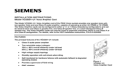
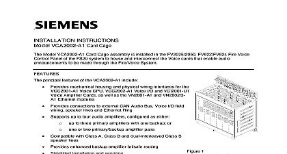
INSTRUCTIONS VCC2002 A1 Voice input Output Card Model VCC2002 A1 Voice I O card is installed into the FV2025 2050 Fire Voice Control Panel of the system Together with the VCC2001 A1 Voice CPU card and one or more VCI2001 U1 Amplifier it enables voice announcements to be made through the Fire Voice system principal features of the VCC2002 A1 include The internal codec Converts analog audio from microphones Mass Notification MNS and external sources into digital audio signals Converts digital audio signals to analog for use in other parts of system or with external equipment Attenuation and amplification of incoming audio Connections for optional remote microphones and voice switch modules CAN repeater for externally connected modules Channel 1 only Connections for two 2 configurable simultaneous audio input and two 2 audio output channels 1 internal and 1 24VDC power distribution current limiting and short circuit for modules connected to the Card Cage 1 I O Card Operational status via LED displays Two volume controls Future use EMC compliant Can be used in the UL and ULC market ROHS compliant and meets performance specifications within the industrial temperature installing the VCC2002 A1 Voice I O Card into the VCA2002 A1 Card Cage set the jumpers on card to either supervise or not supervise the input and output audio lines Supervision refers to the monitoring of signal lines for short or open circuit conditions A supervised line will have an EOL resistor at the end of the line to set a DC bias level When the resistor is present the voltage is at a certain value This DC voltage level will change if the line is either open circuited or This DC bias voltage is monitored by an analog to digital converter which enables the system to all the voltage levels and determine if a short or open has occurred 2 illustrates the locations of the jumpers on the Voice I O Card and Table 1 lists the jumper that are used to activate supervision for the input and output channels Both jumpers for each must be in the same position either supervised or unsupervised for the card to operate en b 1 Supervision Selected for All Channels 2 on VCC2002 A1 voice I O Card 2 All Channels Unsupervised Position for Channel Position Unsupervised Input 1 Input 2 Output 1 Settings on VCC2002 A1 Voice I O Card for Supervised Channel Operation en b equipment is compatible with the 18VDC supervision voltage supervised audio input lines are to be implemented ensure that any connected refer to Figure 3 primary functions of the VCC2002 A1 Voice I O Card are to with the VTO2004 U2 U3 Microphone Module and the VTO2001 U2 U3 Option Module Switches Provide analog to digital conversion of announcements routed to the VCC2001 A1 Voice CPU Card Provide digital to analog conversion of announcements routed from the VCC2001 A1 Voice CPU to external announcement devices Distribute and supervise 24VDC power Provide DC supervision of external wiring Provide a CAN bus repeater functionality 3 Voice I O Card Flow Diagram EXTERNAL OPTION MODULES OR EXTERNAL AUDO SOURCEFROM VTO2004INTERNAL OPTION MODULE MICROPHONE CONFIGURABLE SUPERVISED SWITCH INPUTS24VDC POWER DISTRIB TO INTERNAL OPTION MODULESTO EXTERNAL OPTION MODULE S X401X402X102 24 VOLT DC INPUTAUDIO HANDLINGCH1 INX102CH 2 ININTERNAL AUDIO INX401X402CH 1 OUTX102INTERNAL AUDIO OUTX403CODECCAN BUSCPLD CAN REPEATERVCC2001 A1 VOICE CPU CARDDIGITAL AUDIO OUTDIGITAL AUDIO INTO EXTERNAL OPTION MODULESSWITCH INPUTS RELAY OUTPUTX403X403X403SWITCH 1 INSWITCH 2 INAUDIO ACTIVE OUTTO BOOSTER AMPIFIER or OPTION MODULES FUTURE NOT USEDCAN BUSI2C BUSCAN BUSX102TO FROM VCC2001 A1 VOICE CPU CARDTO INTERNAL OPTION MODULESX401FROM EXTERNAL OPTIONMODULESNOT USEDTO OPTIONAL AUDIO SYSTEMSfirealarmresources com and Indicators VCC2002 A1 VCC I O Card contains Eight diagnostic LEDs One Power LED of these indicators are located along the card edge and visible through the Card Cage front cover ID 1 Active 1 Fault 2 Active 2 Fault Out Active Green Out Fail Fail Fail Out Fail 1 Active 1 Fault 2 Fault 2 Fault Output Output Fault or CAN Fault failure Power Output Fault 2 VCC A1 Indicator LED States and Meaning 4 VCC2002 A1 LEDS Inputs Relay Output general purpose contact closure inputs and one relay closure output are available to from the VCC I O Either switch input can be used to indicate the presence of an external analog signal on the Channel 2 input if used The contact closure output is used to indicate that the output audio from the system is switch 1 and switch 2 A resistive 680 contact closure must be provided by an external source This closure may be connected to either switch input This will indicate to the system that analog audio signal is applied to the audio input channel A closed contact indicates that the audio to the channel is active while an open contact means that the audio input is inactive A second set contacts can be optionally used for other purposes as needed A relay contact output on the VCC I O card closes to indicate to an external device that the output is active When the audio output is active the relay contact is closed When there is no output the relay contact is open This is an isolated contact closure The external connected must supply its own voltage to monitor the state of the relay contact electrical power prior to working on equipment mount the VCC I O in the card cage Open the inner door of the FV2025 2050 Fire Voice Control Panel Unscrew the latch on the center bottom of the Card Cage front cover and slide the cover up it clears the Card Cage assembly CONTROL FUTURE USE HANDLE 5 Voice I O Card Showing Handle and Volume Controls Refer to Figure 5 Holding the VCC2002 A1 so the two volume control potentiometers are on of the card gently insert the card into the backplane connector marked X201 furthest left of the card cage Use the raised channel guides on the inside top and bottom of the Cage to guide it into place inserting the VCC2002 A1 into the backplane connector avoid using the top and of the card cage for leverage Instead push gently on the center of the molded card handle until the card snaps into place Be sure that the card is to the front of the Card Cage and is positioned between the two indented cards guides in the top and bottom of the Card Cage The card needs to be all three sets of card guides as it is slid into place to correctly mate with the connector avoid damaging the VCC2002 A1 card or the backplane connector DO NOT FORCE CARD INTO POSITION Replace the Card Cage cover by re inserting it into the top of the cage and sliding it downward it reaches the bottom of the assembly Screw the latch back into the Card Cage cover the Voice I O Card from the Card Cage First remove power from the Card Cage Unscrew the latch on the center bottom of the VCA2002 A1 Card Cage front cover and slide Grip the VCC2001 A1 Card by the molded plastic card handle and pull the card gently out of cover up backplane connector Replace the Card Cage cover and reinsert the latch