Autocall 4100ES IDNet 2, IDNet 2+2 and IDNet Loop card Installation Manual

File Preview
Click below to download for free
Click below to download for free
File Data
| Name | autocall-4100es-idnet-2-idnet-2-2-and-idnet-loop-card-installation-manual-6791320584.pdf |
|---|---|
| Type | |
| Size | 4.15 MB |
| Downloads |
Text Preview
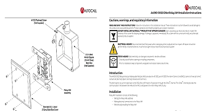
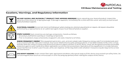
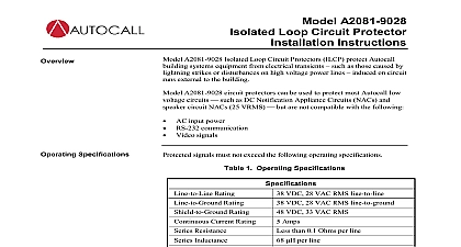
A100 3109 IDNet 2 A100 3110 IDNet 2 2 and A100 3111 IDNet Loop card Installation Instructions warnings and regulatory information AND SAVE THESE INSTRUCTIONS Follow the instructions in this installation manual These instructions must be followed to avoid damage to product and associated equipment Product operation and reliability depend upon proper installation NOT INSTALL ANY AUTOCALL PRODUCT THAT APPEARS DAMAGED Upon unpacking your Autocall product inspect the of the carton for shipping damage If damage is apparent immediately file a claim with the carrier and notify an authorized product supplier HAZARD Disconnect electrical field power when making any internal adjustments or repairs All repairs should be by a representative or an authorized agent of your local Autocall product supplier HAZARD Static electricity can damage components Handle as follows Ground yourself before opening or installing components Prior to installation keep components wrapped in anti static material at all times SAFETY HAZARD Under certain fiber optic application conditions the optical output of this device may exceed eye safety limits Do use magnification such as a microscope or other focusing equipment when viewing the output of this device ACID WARNING Battery contains sulfuric acid which can cause severe burns to the skin and eyes and can destroy fabric any leaking or damaged battery while wearing appropriate protective gear If you come in contact with sulfuric acid immediately skin or eyes with water for 15 minutes and seek immediate medical attention RULES AND REGULATIONS PART 15 This equipment has been tested and found to comply with the limits for a Class A digital device pursuant Part 15 of the FCC Rules These limits are designed to provide reasonable protection against harmful interference when the equipment is operated a commercial environment This equipment generates uses and can radiate radio frequency energy and if not installed and used in accordance the instruction manual may cause harmful interference to radio communications Operation of this equipment in a residential area is likely to harmful interference in which case the user will be required to correct the interference at his own expense REACCPTANCE TEST AFTER SOFTWARE CHANGES To ensure proper system operation this product must be tested in accordance with after any programming operation or change in site specific software Reacceptance testing is required after any change addition or deletion system components or after any modification repair or adjustment to system hardware or wiring All components circuits system operations or functions known to be affected by a change must be 100 tested In addition to ensure that other operations are not inadvertently affected least 10 of initiating devices that are not directly affected by the change up to a maximum of 50 devices must also be tested and proper system verified 72 is a registered trademark of the National Fire Protection Association IDNet 2 card provides the Fire Alarm Control Panel FACP with one IDNet Signaling Line Circuit SLC or channel and with up to isolated loop outputs This card is used with compatible IDNet devices and allows the system CPU to communicate with to 250 initiating devices such as smoke sensors and pull stations IDNet communications provide overall operation improvement isolated output loops allow a short circuit on one loop to avoid the other loops are two available configurations for the IDNet 2 card A100 3109 IDNet 2 card This is the basic configuration which the FACP with two Class B DCLB or Class A DCLA or X DCLC loop outputs that are isolated from each other as A100 3110 IDNet 2 2 card In this configuration the A100 3109 2 card is fitted with two A100 3111 IDNet Loop cards and the FACP with four Class B DCLB or Class A DCLA Class X DCLC isolated IDNet loops Two isolated loops are by the card and one isolated loop is added per IDNet card Unless specified otherwise the term 2 is used in this manual to both the IDNet 2 and the IDNet 2 2 cards The A100 3111 IDNet Loop daughter card can be purchased separately and placed on a pre installed IDNet 2 card that is not EPS mounted once it is added to the IDNet card the compatibility and programming requirements will become the same as with the IDNet 2 2 card Verify FACP system programmer executive and slave software compatibility when installing or replacing system components Refer to the Support Information and Downloads website for compatibility information Rev F IDNet 2 A100 3110 IDNet 2 2 and A100 3111 IDNet Loop card Installation Instructions Layout compatibility 2 4100ES bays EPS modules 4100U bays 2 2 4100ES bays 4100U bays ES PS modules compatibility use with revision 2.04 or higher of the ES Panel Programmer Software and revision 12.08 of the 4100U Programmer and Master software Layout IDNet 2 is a standard 4x5 card that can accommodate two IDNet Loop cards Figure 1 highlights the feature elements of these cards 1 Card Layout 2 Rev F IDNet 2 A100 3110 IDNet 2 2 and A100 3111 IDNet Loop card Installation Instructions Identification IDNet 2 Card is equipped with 8 LEDs that report the card troubles Table 1 identifies and describes the different LEDs 1 LED Definition description a trouble occurs on a loop the LED corresponding to that loop Map Name A B C D Off Illuminates to indicate a negative earth fault Off Illuminates to indicate a positive earth fault off Illuminates to indicate a problem with the IDNet channel Steady on indicates channel failure off Turns on steady if the card is not communicating with the CPU the Address DIP Switch SW1 is used to set the IDNet 2 card address as identified in the Panel Programmer job see the section on Programming for more From left to right these switches are designated as SW1 1 through SW1 8 The function of these switches is as follows SW1 1 This switch sets the baud rate for the internal communications line running between the card and the CPU Set this switch to ON SW1 2 through SW1 8 These switches set the card address within the FACP Refer to Figure 3 for a complete list of the switch settings for all the possible card addresses must set these switches to the value assigned to the card by the Panel Programmer 2 DIP Switch SW1 3 Rev F IDNet 2 A100 3110 IDNet 2 2 and A100 3111 IDNet Loop card Installation Instructions 3 A100 3109 IDNet 2 Card Addresses 4 Rev F IDNet 2 A100 3110 IDNet 2 2 and A100 3111 IDNet Loop card Installation Instructions IDNet 2 card and the IDNet 2 2 card mount onto the Power Distribution Interface PDI in an FACP expansion cabinet The IDNet 2 card can also installed in the expansion slot of an ES Power Supply Card ES PS card mount the IDNet 2 and IDNet 2 2 card Select an empty PDI connector Insert the washer and the metal standoffs into the corresponding installation holes Use the provided hardware to secure the card the PDI connector on the back of the card into the PDI connector 4 Mounting an IDNet 2 or IDNet 2 2 card IDNet 2 card shown add IDNet Loop cards to an IDNet 2 card Remove the screws that attach the IDNet 2 card to the panel Use the provided hardware to secure the card the metal standoffs and the plastic standoffs into the corresponding installation holes the connector on the back of the IDNet Loop card into the connector on the IDNet 2 card and snap it in place with the plastic standoff When adding IDNet Loop cards to a pre installed IDNet 2 card it is important to remember that the properties of the IDNet 2 card must be in the FACP programmer 5 Adding an IDNet Loop Card to an IDNet 2 Card 5 Rev F IDNet 2 A100 3110 IDNet 2 2 and A100 3111 IDNet Loop card Installation Instructions Overview IDNet output from the IDNet 2 2 card can be wired as either an isolated Class A DCLA circuit a Class X DCLC circuit or as two isolated Class DCLB circuits A DCLA wiring provides an alternate communication path that allows communication to all devices to be maintained when a single open fault occurs Class A wiring requires two wires to be routed from the Primary Terminals B B to each device and then back to the Secondary A A Wiring is in out tapping is not allowed B DCLB wiring allows tapping IDNet wiring is inherently supervised due to individual device level communications End of line resistors are