Autocall A4090-9117 Addressable Power Isolator with IDNet Communications Control

File Preview
Click below to download for free
Click below to download for free
File Data
| Name | autocall-a4090-9117-addressable-power-isolator-with-idnet-communications-control-5679231048.pdf |
|---|---|
| Type | |
| Size | 1.52 MB |
| Downloads |
Text Preview
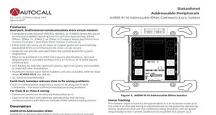
Datasheet Peripherals Addressable Power Isolator with IDNet Communications Control 1 Addressable Power Isolator with IDNet Control shown approximately 1 2 size ULC CSFM Listed FM port bi directional power isolator for use with Autocall 4010ES 4100ES Series fire alarm control panels Either port can serve as an input or output ports are automatically when a power wiring short circuit or a low voltage condition Isolation can also be activated from the control panel for system For use with fire alarm control panel system power rated for up to 2 A 32 VDC Isolators communicate their location specific address and status and control via IDNet communications Small size fits into 4 square electrical box and allows convenient where protection is required Visible LED flashes to indicate communications optional covers are to view LED after installation fault isolation reduces time to fix wiring problems Built in control panel diagnostics can activate the addressable power assisting in locating earth fault conditions the most common wiring problem Class B or Class A power wiring Power is monitored from either port Two Isolators can be connected to produce Class A power wiring that optimize operation by maintaining connection with devices outside the isolated wiring section listed to Standard 864 Circuit Isolation normal conditions the A4090 9117 Addressable Power Isolator continuity between ports In the event of a short circuit or requested from the control panel the isolator opens a two pole switch isolating both power circuit conductors power up in isolation mode and are directed to connect by the panel If the output wiring is acceptable the isolator will connect the rest of the circuit If the output wiring is shorted the isolator isolated Tracking isolator reports to the panel when it is in isolation mode and the of shorted wiring is available at the panel by identifying non device addresses Isolators are assigned sequentially to number addresses to expedite Signaling Line Circuit SLC power up to Installation Instructions 574 873AC for additional information Faults system installation earth faults frequently occur Finding these normally requires extensive wiring disconnection With the Power Isolator earth faults on fire alarm system power can be more quickly located to expedite repair This product has been approved by the California State Fire Marshal CSFM pursuant to Section 13144.1 of the California Health and Safety Code See CSFM Listings 7300 2269 0506 and for allowable values and or conditions concerning material presented in this document Additional listings may be applicable contact your local product supplier for the latest status Rev 9 03 2021 Addressable Power Isolator with IDNet Communications Control 1 Product Selection Power Isolator semi flush mounted box surface mounted box trim plate with LED viewing window includes mounting galvanized steel Selection Rating Power Connections Wiring Range Communications Wiring 2 Electrical A maximum 32 VDC maximum mA maximum 24 VDC system power communications 1 address one unit load terminals for input and output wiring 18 to 14 AWG 0.82 mm2 to 2.08 mm2 wires terminal up to 12 AWG 3.31 mm2 one wire terminal 3 Wiring reference to individual devices for wiring distances with A2081 9028 Circuit Protector to 2500 ft 762 m from fire alarm control to 10,000 ft 3048 m total wiring distance including T Taps with A2081 9044 Overvoltage Protectors 4 Mechancial H x 4 1 8 W x 1 3 8 D 105 mm x 105 mm x 35 mm to 120 F 0 to 49 C indoor operation only to 90 RH at 90 F 32 C 2 Rev 9 03 2021 Addressable Power Isolator with IDNet Communications Control Isolator Multi Floor Example 1 Circuit Isolation The one line diagram on this page shows a multiple floor example with Class B IDNet communications and conventional B power wiring Each floor wiring starts at an isolator If any floor wiring beyond the isolator experiences a short circuit each floor will be separated from the next preventing the short circuit from disabling the entire wiring run Fault Isolation In the event of an earth wiring fault each floor power wiring can be individually isolated using control panel diagnostics This the search area by disconnecting the isolated wiring section and can result in decreasing the time required to locate and correct the earth IDNet Addressable Power Isolator 2 Isolator Multi Floor Example 1 5 Figure key sensor with relay base IDNet Addressable Isolator IDNet isolators are shown for typical reference but are not required This is a one line drawing showing only IDNet communications and power wiring Operation of the A4090 9117 Addressable IDNet Power Isolator requires connection to a 4100ES 4010ES 4007ES IDNet communications 3 Rev 9 03 2021 Addressable Power Isolator with IDNet Communications Control Isolator Multi Floor Example 2 A Wiring The illustration below is a modification of Example 1 Each floor wiring loop connects to the next floor in a Class A connection From last device the wiring returns to the panel providing a secondary path that is monitored for loop integrity Class A power wiring is available from 4100ES 4010ES 4007ES Fire Control Panel programmed for this application using two A4090 9117 Power Isolators mounted close nippled at the Assistance It is recommended that for Class A wiring isolators be located as the first and last devices in the loop as shown below With resulting wiring isolation flexibility locating earth wiring faults can be made easier IDNet Addressable Power Isolator 3 Isolator Multi Floor Example 2 6 Figure key sensor with relay base IDNet Addressable Isolator IDNet isolators are shown for typical reference but are not required This is a one line drawing showing power wiring and IDNet communications only Class A power requires using two A4090 9117 Power Isolators close nippled at the panel with Class A operation performed by panel control of the Isolators Operation of the A4090 9117 Addressable IDNet Power Isolator requires connection to a 4100ES 4010ES 4007ES IDNet communications isolators are shown for typical reference but are not required For Class A IDNet SLCs locate isolators as first and last device on the SLC for convenience 4 Rev 9 03 2021 Information Addressable Power Isolator with IDNet Communications Control The A4090 9117 Addressable Power Isolator is shown in Figure 4 4 Reference Double Gang Blank Cover Plate The A4090 9801 Trim plate for semi flush mounted box and the A4090 9802 Trim plate for surface mounted box are shown in Figure 5 5 Trim Plates for Visible LED 5 Rev 9 03 2021 Addressable Power Isolator with IDNet Communications Control 2021 Johnson Controls All rights reserved All specifications and other information shown were current as of document revision and are subject to change without notice listings may be applicable contact your local Autocall product supplier for the latest status Listings and approvals under Tyco Fire Security GmbH and the names listed in this material are marks and or registered marks Unauthorized use is strictly prohibited NFPA 72 and National Fire Alarm Code are registered of the National Fire Protection Association NFPA Rev 9 03 2021