Autocall Addressable Duct Sensor Housings with TrueAlarm Photoelectric Sensor; Available with Multiple Relay Control

File Preview
Click below to download for free
Click below to download for free
File Data
| Name | autocall-addressable-duct-sensor-housings-with-truealarm-photoelectric-sensor-available-with-multiple-relay-control-4975281360.pdf |
|---|---|
| Type | |
| Size | 2.82 MB |
| Downloads |
Text Preview
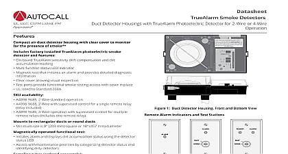
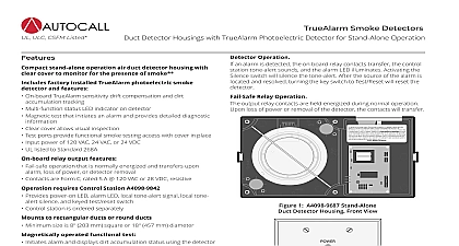
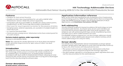
Datasheet Analog Sensing Duct Sensor Housings with TrueAlarm Photoelectric Sensor Available with Relay Control ULC CSFM Listed FM air duct sensor housing with clear cover to monitor for presence of smoke factory installed TrueAlarm photoelectric smoke sensor features Individual sensor information processed by the host control panel to sensor status Digital transmission of analog sensor values via IDNet 2 wire Programmable sensitivity consistent accuracy environmental status testing and monitoring of sensor dirt A4098 9755 Basic duct sensor housing no relay output powered by IDNet A4098 9756 Duct sensor housing with supervised output for multiple remote relays separate 24 VDC includes one relay Relay output is under panel control At the panel relay output can be activated manually or in response to a alarm or other input features UL listed to Standard 268A Clear cover allows visual inspection Test ports provide functional smoke testing access with cover in place Mounts to rectangular ducts or round ducts minimum size is 8 203 square or 18 457 mm diameter Magnetic test feature for alarm initiation at housing Optional weatherproof enclosure is available separately refer to data AC4098 0032 LEDs on interface board Red Alarm Trouble LED for sensor status and communications polling Yellow LED for open or shorted trouble indication of supervised relay A4098 9756 only tubes ordered separately Available in multiple lengths to match duct size Installed and serviced with housing in place module options ordered separately Remote red status alarm LED A2098 9808 Remote test station with LED A2098 9806 4098 9843 remote relays refer to Duct Sensor Selection Chart 1 Sensor Housing Front and Bottom View 2 3 Autocall compact air duct smoke sensor housings provide operation for the detection of smoke in air conditioning or ducts Sampling tubes are installed into the duct allowing air be directed to the smoke sensor mounted in the housing This product has been approved by the California State Fire Marshal CSFM pursuant to Section 13144.1 of the California Health and Safety Code See CSFM Listings 3240 2269 0526 7272 2269 0537 7300 2269 0551 and for allowable values and or conditions concerning material presented in this document Additional listings may be applicable contact your local Autocall product supplier for latest status Rev 12 03 2021 Duct Sensor Housings with TrueAlarm Photoelectric Sensor Available with Multiple Relay Control Sensor Operation Communication of Analog Sensing Analog information from the sensor is digitally communicated to the control panel where it is analyzed input is stored and tracked as an average value with an alarm or abnormal condition being determined by comparing the sensor present against its average Data Evaluation Monitoring each photoelectric sensor average value provides a software filtering process that compensates for factors dust dirt etc and component aging providing an accurate reference for evaluating new activity The result is a significant in the probability of false or nuisance alarms caused by shifts in sensitivity either up or down Panel Selection Peak activity per sensor is stored to assist in evaluating specific locations The alarm set point for each sensor is determined the control panel selectable as the individual application requires Status LED Each sensor housing red status LED located on the electrical interface board pulses to indicate communications with the If the control panel determines that a sensor is in alarm or that it is dirty or has some other type of trouble the details are annunciated at the panel and that sensor housing status LED will be turned on steadily During a system alarm the control panel will control the LEDs such that LED indicating a trouble will return to pulsing to help identify any alarmed sensors Remote Status Alarm LEDs track the operation of the sensor LED Please note that smoke detection in air ducts is intended to provide notification of the presence of smoke in the duct It is not intended to and will replace smoke detection requirements for open areas or other non duct applications Sensing photoelectric sensors use a stable pulsed infrared LED light source and a silicon photodiode receiver to provide consistent and accurate power smoke sensing duct sensor applications require less sensitive settings such as 2.5 per foot obscuration due to the ducts being a relative dirty However the standard seven levels of TrueAlarm sensor sensitivity are available for each individual sensor ranging from 0.2 to 3.7 foot of smoke obscuration Sensitivity is selected and monitored at the fire alarm control panel Alarm Control Panel Features Individual smoke sensitivity selection Sensitivity monitoring that satisfies NFPA 72 sensitivity testing requirements Peak value logging allows accurate analysis for sensitivity selection Automatic once per minute individual sensor calibration check verifies sensor integrity Automatic environmental compensation Smoke sensitivity is displayed in percent per foot Ability to display and print detailed sensor information in plain English language Relays of model A4098 9756 are under panel control for ON OFF or override Sensor Selection Chart 1 Duct Smoke Sensor Housing with Photoelectric Sensor Duct Sensor Housing operating power is supplied by either no relay output Sensor Housing with supervised multiple relay output requires 24 VDC fire alarm power and A4081 9008 end of line harness includes one 4098 9843 relay 4010ES 4100ES 4100E output is for up to 15 total 4098 9843 Relays additional are ordered separately 2 Remote LED Indicator and Test Station Select One if Required LED status indicator on single gang stainless steel plate Station with keyswitch and red LED status indicator on single gang steel plate turning switch to TEST initiates alarm for system single gang box 3 H x 2 W x 2 76 mm x 51 mm x 51 mm 3 Epoxy Encapsulated Remote Relay and End of Line Resistor only up to 15 single Form C 7 A 120 VAC refer to pages 3 and 4 for relay information one included with A4098 9756 wiring is 18 0.82 mm2 color coded wire leads Resistor Harness 10 k 1 2 W ref 733 894 required to remote relay coil connection relays within 3 ft 1 m of being controlled per NFPA last relay location Each duct housing includes an internally mounted model A4098 9714 TrueAlarm photoelectric sensor and an exhaust tube A correctly sized tube ordered per application is required refer to chart below 2 Rev 12 03 2021 Duct Sensor Housings with TrueAlarm Photoelectric Sensor Available with Multiple Relay Control Tube Selection Chart Ordered Separately Per Duct Width Select One Duct Width 305 mm to 23 330 mm to 584 mm to 46 610 mm to 1168 mm to 71 1168 mm to 1803 mm to 95 1803 mm to 2413 mm Cut Length 12.7 mm longer than duct width 12.7 mm longer than duct width in 76 mm longer than duct width in 76 mm longer than duct width in 76 mm longer than duct width Required 3 Rev 12 03 2021 Duct Sensor Housings with TrueAlarm Photoelectric Sensor Available with Multiple Relay Control Sensor Housing Detail Reference Refer to Installation Instructions 574 776AC for additional installation detail and maintenance information A4098 9756 only 4 Sensor Housing Detail Reference 4 Rev 12 03 2021 Duct Sensor Housings with TrueAlarm Photoelectric Sensor Available with Multiple Relay Control Sensor Location Reference Sensor Location Considerations Proper duct smoke detection location must ensure adequate airflow within the duct housing Duct air velocity rating is 300 to 4000 ft min 91 to 1220 m min Pressure differential between intake and exhaust tubes is required to be 0.015 to 1.55 inches of water 0.381 to 39.37 mm Ensure accessibilit