Autocall Addressable Manual Stations Single and Dual Action
File Preview
Click below to download for free
Click below to download for free
File Data
| Name | autocall-addressable-manual-stations-single-and-dual-action-0839462175.pdf |
|---|---|
| Type | |
| Size | 1.88 MB |
| Downloads |
Text Preview
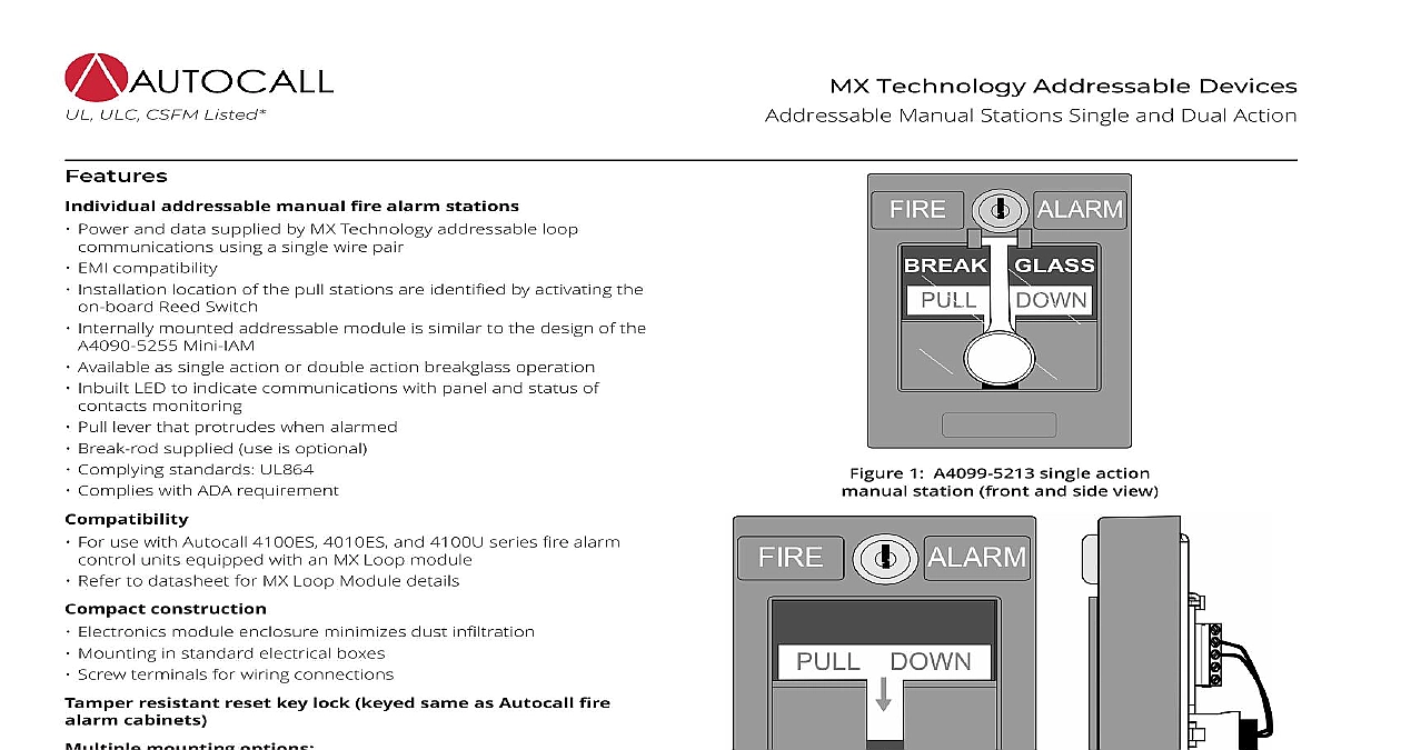
MX Technology Addressable Devices Manual Stations Single and Dual Action 1 single action station front and side view 2 double breakglass manual station ULC CSFM Listed addressable manual fire alarm stations Power and data supplied by MX Technology addressable loop using a single wire pair EMI compatibility Installation location of the pull stations are identified by activating the Reed Switch Mini IAM Internally mounted addressable module is similar to the design of the Available as single action or double action breakglass operation Inbuilt LED to indicate communications with panel and status of monitoring Pull lever that protrudes when alarmed Break rod supplied use is optional Complying standards UL864 Complies with ADA requirement For use with Autocall 4100ES 4010ES and 4100U series fire alarm units equipped with an MX Loop module Refer to datasheet for MX Loop Module details construction Electronics module enclosure minimizes dust infiltration Mounting in standard electrical boxes Screw terminals for wiring connections resistant reset key lock keyed same as Autocall fire cabinets mounting options Surface or semi flush with standard boxes or matching Autocall boxes Flush mount adapter kit Adapters are available for retrofitting to commonly available existing addressable stations contain an integral addressable module that monitors status and communicates with an MX Loop Module in the host fire alarm control unit of the A4099 5213 single action manual station requires firm downward pull to activate the alarm switch Completing the breaks an internal plastic break rod visible below the pull lever is optional The break rod can act as a deterrent to vandalism interfering with the minimum pull requirements needed for easy The pull lever latches into the alarm position and remains out of the housing to provide a visible indication double action stations breakglass Strike the front hammer to break the glass and expose the recessed pull lever pull lever then operates as a single action station reset requires the use of a key to reset the manual station lever deactivate the alarm switch If the break rod is used it must be testing Pull the lever to test the station Electrical testing is by unlocking the station housing to activate the alarm switch This product has been approved by the California State Fire Marshal CSFM pursuant to Section 13144.1 of the California Health and Safety Code See CSFM Listing 7300 2269 0506 for allowable and or conditions concerning material presented in this document Additional listings may be applicable contact your local product supplier for the latest status Rev 2 1 2020 manual station semi flush mounting Manual Stations Single and Dual Action 3 manual station semi flush mounting manual stations surface mounting mounting For surface mounting of these addressable manual stations the preferred electrical boxes are shown in Figure 4 mounting reference Refer to Addressable manual station additional mounting information for wiremold box mounting compatibility 4 mounting 2 Rev 2 1 2020 mount side view with internal detail Manual Stations Single and Dual Action 5 detail reference to NFPA 72 the National Fire Alarm and Signaling Code and all applicable local codes for complete requirements for manual stations The summarizes the basic requirements Stations are located in the normal path of exit and distributed in the protected area such that they are unobstructed and readily accessible Mount the operable part not less than 3.5 ft 1.1 m and not more than 4.5 ft 1.37 m above floor level At least one station should be provided on each floor Additional stations should be provided to obtain a travel distance not more than 200 ft 61 to the nearest station from any point in the building When manual station coverage appears limited in any way additional stations should be installed 3 Rev 2 1 2020 manual station additional mounting information retrofit and new installations additional compatible mounting boxes and the required adapter plates are shown in Figure 6 Manual Stations Single and Dual Action manual station flush mounting information 6 mounting information 7 mounting information 4 Rev 2 1 2020 technology addressable manual station product selection 1 Addressable manual stations red housing with white letters and white pull lever action operation action breakglass operation Manual Stations Single and Dual Action and communications means connections listed temperature range range color Lever color dimensions instructions 2 Accessories mount steel box red aluminum surface mount box red trim plate for double gang switch box red trim plate for Wiremold box V5744 2 red mount adapter kit black mount adapter kit beige breakglass break rod cover kit for field installation on A4099 9001 3 Specifications Loop one address per manual station with MX Service Tool blocks for wire size 20 to 14 AWG 0.5 mm2 to 2.5 mm2 to 120 0 to 49 is intended for indoor operation to 93 RH at 100 38 with white raised lettering and pull lever are Lexan polycarbonate or equal with red raised lettering in H x 3.75 in W x 1 in D 127 mm x 95 mm x 25 mm 5 Rev 2 1 2020 Manual Stations Single and Dual Action 2020 Johnson Controls All rights reserved All specifications and other information shown were current as of document revision and are subject to change without notice listings may be applicable contact your local Autocall product supplier for the latest status Listings and approvals under Tyco Fire Security GmbH and the names listed in this material are marks and or registered marks Unauthorized use is strictly prohibited NFPA 72 and National Fire Alarm Code are registered of the National Fire Protection Association NFPA Rev 2 1 2020