Autocall Circuit Protection; Model A2081-9044 Overvoltage Protector
File Preview
Click below to download for free
Click below to download for free
File Data
| Name | autocall-circuit-protection-model-a2081-9044-overvoltage-protector-4132057689.pdf |
|---|---|
| Type | |
| Size | 839.53 KB |
| Downloads |
Text Preview
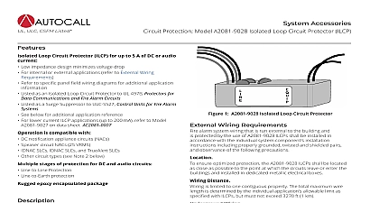
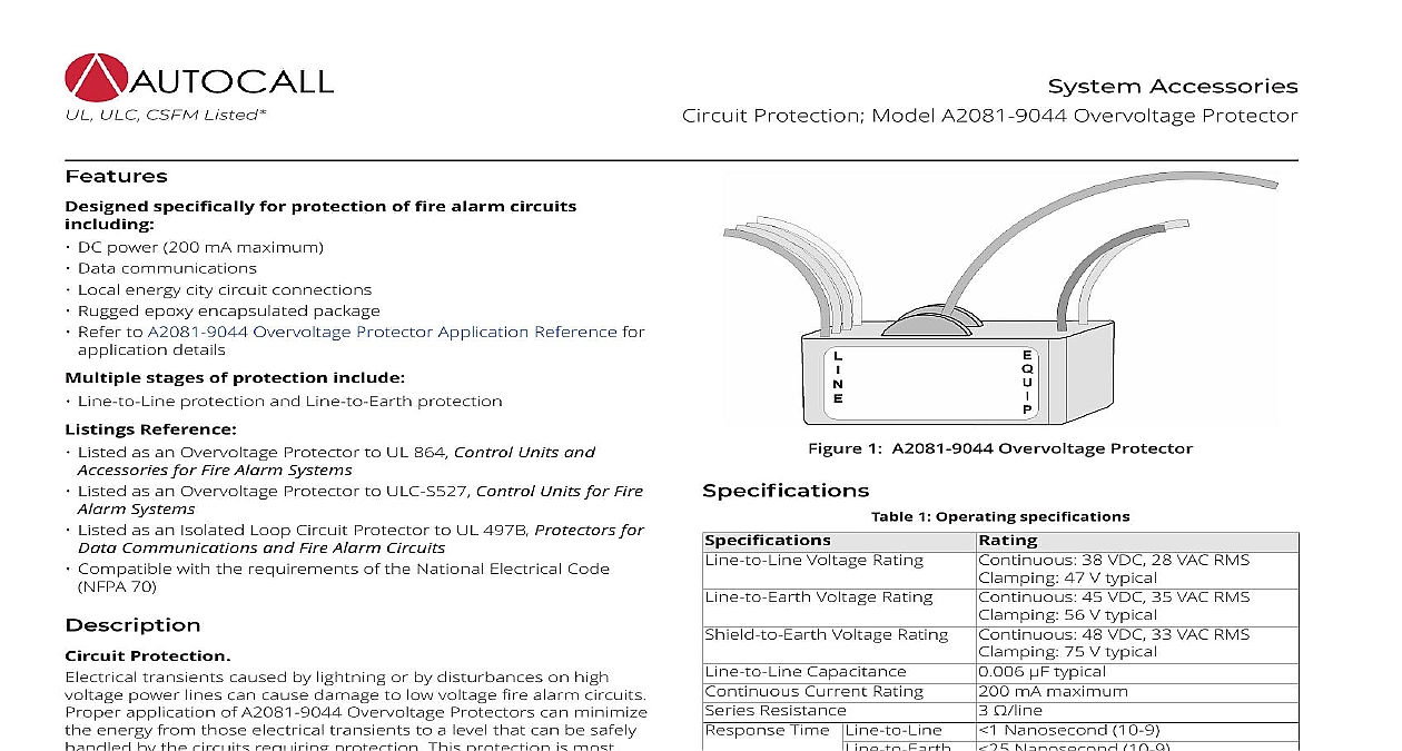
UL ULC CSFM Listed Accessories Protection Model A2081 9044 Overvoltage Protector Listed as an Overvoltage Protector to ULC S527 Control Units for Fire specifically for protection of fire alarm circuits DC power 200 mA maximum Data communications Local energy city circuit connections Rugged epoxy encapsulated package Refer to A2081 9044 Overvoltage Protector Application Reference for details stages of protection include Line to Line protection and Line to Earth protection Reference Listed as an Overvoltage Protector to UL 864 Control Units and for Fire Alarm Systems Systems 70 Listed as an Isolated Loop Circuit Protector to UL 497B Protectors for Communications and Fire Alarm Circuits Compatible with the requirements of the National Electrical Code Protection transients caused by lightning or by disturbances on high power lines can cause damage to low voltage fire alarm circuits application of A2081 9044 Overvoltage Protectors can minimize energy from those electrical transients to a level that can be safely by the circuits requiring protection This protection is most when placed at the locations where the circuits leave and enter A2081 9044 Overvoltage Protector provides multiple stages of against electrical transients The small package size allows it be easily mounted at the location that achieves maximum protection Wiring Requirements alarm system wiring that is run external to the building and is by A2081 9044 Overvoltage Protectors shall be installed accordance with the individual system component s installation including properly grounded twisted and shielded wire and observance of the following precautions To ensure optimized protection the A2081 9044 Overvoltage shall be located as close as possible to the point at which the leave or enter the buildings and installed in dedicated metallic boxes distance is limited to one contiguous property The total wire length is determined by the individual application s limit as specified with overvoltage protectors but must not 3270 ft 1 km grounding conductor shall be 12 AWG with a maximum length of ft 8.5 m run in as straight a line as possible and connected to the grounding electrode system per NFPA 70 the National Electrical 1 Overvoltage Protector 1 Operating specifications Voltage Rating Voltage Rating Voltage Rating Capacitance Current Rating Resistance Time 38 VDC 28 VAC RMS 47 V typical 45 VDC 35 VAC RMS 56 V typical 48 VDC 33 VAC RMS 75 V typical typical mA maximum Nanosecond 10 9 Nanosecond 10 9 A 10 x 50 pulse A 8 x 20 pulse 5000 A 10 x 50 2 Mechanical specifications box requirement Rating Rating Leads Lead Instructions 7 16 in W x 1 3 8 in D x 1 1 16 H 62 mm x 35 mm x 27 mm epoxy encapsulated in 102 mm square box 2 1 8 in mm minimum depth to 120 0 to 49 RH at 30 coded 18 AWG 0.82 mm in long 245 mm 14 AWG 10 in long 254 This product has been approved by the California State Fire Marshal CSFM pursuant to Section 13144.1 of the California Health and Safety Code See CSFM Listings 7300 2269 0507 and for allowable values and or conditions concerning material presented in this document Additional listings may be applicable contact your local Autocall product supplier for the latest Rev 5 1 2020 Protection Model A2081 9044 Overvoltage Protector Overvoltage Protector Application Reference A2081 9044 Overvoltage Protector is for fire alarm circuit use as listed below These circuits may be standard or optionally available on the Fire Alarm Control Panel Series 4007ES 4010ES 4100ES Applications listed for remote device output circuits include the applicable device number below the description 3 Compatible Fire Alarm Control Panel Circuits Distance and Requirements A2081 9044 s 2500 ft 762 m maximum Four A2081 9044 s 1500 ft 457 m maximum Type Communications ZAM IDC A4090 9101 and IAM Zone A4090 9001 and Communications Alarm Network Wired and TrueAlert SLCs risers Communications 4010 Series Models ft 428 m maximum ft 122 m maximum maximum line distance by 1000 ft 305 m for first two suppressors each additional suppressor distance by 500 ft 152 m of two per node to node connection no impact to total distance limit mA maximum current 2500 ft 762 m total length on branch with suppressor 6 of line resistance be accounted for in voltage drop calculations Maximum of two suppressors on a branch Do not mix with A2081 9028 Isolated Loop Circuit Protector ILCP VRMS Audio only limited to 200 mA A2081 9044 s 2500 ft 762 m maximum Four A2081 9044 s 1500 ft 457 m maximum Precautions for All Circuit Types subject to local codes wiring must be in a wiring trough that is separate from commercial power distribution wiring wiring must be run on poles separate from those supporting any commercial power distribution wiring Wiring shall be run in parallel with commercial power distribution wiring and be separated by a minimum distance of either 100 ft 30 m or the maximum span between any two poles of either the system s circuit or the commercial power distribution circuit Connection Reference refer to Installation Instructions 574 832AC for additional information 2020 Johnson Controls All rights reserved All specifications and other information shown were current as of document revision and are subject to change without notice listings may be applicable contact your local Autocall product supplier for the latest status Listings and approvals under Tyco Fire Security GmbH and the names listed in this material are marks and or registered marks Unauthorized use is strictly prohibited NFPA 72 and National Fire Alarm Code are registered of the National Fire Protection Association NFPA Rev 5 1 2020