Autocall Electronic Heat Detectors for Two-Wire and Four-Wire Bases

File Preview
Click below to download for free
Click below to download for free
File Data
| Name | autocall-electronic-heat-detectors-for-two-wire-and-four-wire-bases-9427531680.pdf |
|---|---|
| Type | |
| Size | 681.76 KB |
| Downloads |
Text Preview
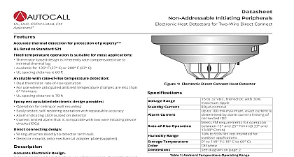
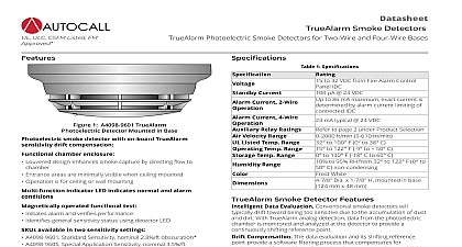
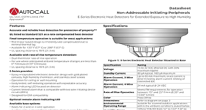
Datasheet Initiating Peripherals Heat Detectors for Two Wire and Four Wire Bases Reference detectors are used where property protection is desired and life safety protection is not required or is performed by other Typical heat detector applications are satisfied by use of fixed temperature electronic detectors addition of rate of rise operation provides two forms of heat for use where temperature fluctuations are controlled and less than 6 F min 3.33 C min Where temperatures may fluctuate quickly use fixed temperature detection to NFPA 72 the National Fire Alarm Code and publication A4098 Detectors Sensors and Bases Application Manual for guidance in applying and locating heat detectors Current Current 2 Wire Current 4 Wire Operation Range 1 General Specifications to 32 VDC filtered DC with 30 ripple typical 100 maximum to 86 mA maximum exact current is by alarm current limiting of IDC mA typical 24 VDC FM requirements for operation 15 and 25 F min 8.33 and C min to 95 RH from 32 to 122 F 0 50 C not intended for outdoor to 140 F 18 C to 60 C to Temperature Temperature Operating Range F Models F Models to 100 F 0 to 38 C to 150 F 0 to 66 C In most fires hazardous levels of smoke and toxic gas build up before a heat detection device would initiate an alarm In where Life Safety is a factor the use of smoke detection is highly Temperature Guidelines F 57 C fixed temperature detectors are for normal temperatures do not exceed 100 F 38 C F 93 C fixed temperature detectors are for normal temperatures exceed 100 F 38 C but are less than 150 F 66 C Indicating LED Operation heat detector LED turns ON continuously when in alarm During conditions the LED is OFF ULC CSFM Listed FM 1 Heat Detector Mounted in Base and reliable heat detection for protection of property listed to Standard 521 as a rate compensated heat detector temperature operation is suitable for most applications Thermistor based design is inherently rate compensated due to thermal lag Available for 135 F 57 C or 200 F 93 C UL and ULC spacing distance is 70 ft 21.3 m with rate of rise temperature detection Dual thermistor rate of rise operation For use where anticipated ambient temperature changes are less than F minute 3.33 C minute UL and ULC spacing distance is 70 ft 21.3 m encapsulated electronic design provides Operation for ceiling or wall mounting Easily tested self restoring operation with repeatable accuracy Alarm indicating LED located on detector Current limited alarm that is compatible with two wire initiating device IDCs Designed for EMI compatibility remote alarm indicating LED base options Bases for 2 wire or 4 wire operation Auxiliary relay output refer to selection chart on page 2 for relay Remote alarm indicating LED output Electronic Design electronic heat detectors use a fast response thermistor based to provide temperature sensing that quickly accurately and identifies when fixed temperatures are exceeded The temperature sensing thermistor readily tracks the local ambient This eliminates the time required to melt a lead pellet or a bimetallic element as occurs in mechanical heat detector designs provides the required heat detection for most applications detection detection is determined by comparing two thermistor By combining accurate thermistors with proper physical this patented rate of rise detection design achieves a high of performance not normally available with mechanical detection This product has been approved by the California State Fire Marshal CSFM pursuant to Section 13144.1 of the California Health and Safety Code See CSFM Listings 7300 2269 0551 7270 2269 0511 and 7300 2269 0550 for allowable values and or conditions concerning material presented in this document Additional listings may be applicable contact your local product supplier for the latest status Rev 12 03 2021 Heat Detectors for Two Wire and Four Wire Bases Verification Application Note connecting these electronic heat detectors to a 2 wire initiating device circuit IDC that is providing Alarm Verification for smoke detectors the A4098 9682 4 wire base The 4 wire base provides an alarm contact that is not current limited Heat detectors in the 2 wire base present a alarm condition that is not compatible with Alarm Verification Initiating devices other than smoke detectors are required to activate the without starting the alarm verification cycle Detector Selection Chart compatible with bases listed below Operation at Ratings Ulc Spacing Response Time Index Spacing F 57 C F 93 C F 57 C F 93 C applicable ft x 20 ft 6.1 m x 6.1 m 15 25 F min 13.88 C min ft x 20 ft 6.1 m x 6.1 m ft x 50 ft 15.2 m x 15 2 m Ultra Fast ft x 70 ft 21.3 m x m Detector Base Selection Chart Base no options Base with connection remote LED alarm indicator connections connections Base with auxiliary relay output be connected as the only on the IDC to ensure operation Base with auxiliary relay output Requires separate 24 power connections Operation Type Type connections connections Operation Type limited Type connections connections connections wire equivalents 18 AWG 0.82 mm2 14 AWG 2.08 mm2 Form C contacts for suppressed loads terminals for in out wiring 18 to 14 AWG terminals for 18 to 14 AWG for in out wiring of zone color 18 AWG leads for in out wiring of zone coded 18 AWG leads Ratings A 28 VDC A 120 AC Connections terminals for 18 to 14 AWG for in out wiring of zone color 18 AWG leads for in out wiring of zone coded 18 AWG leads Ratings A 28 VDC A 120 AC Connections coded 18 AWG leads for in out wiring coded 18 AWG leads terminals for 18 to 14 AWG for in out wiring of power color 18 AWG leads for in out wiring of power Form C contacts for suppressed loads 2 Rev 12 03 2021 Heat Detectors for Two Wire and Four Wire Bases Detector Accessories Plate Red LED Alarm Relay Relay wire equivalent 18 AWG 0.82 mm2 2 Heat Detector Accessories for surface or semi flush mounting to 4 102 mm square electrical or for surface mounting to 4 octagonal box also be used when retrofitting to replace existing larger diameter bases on single gang stainless steel plate wiring connections are 18 AWG coded leads encapsulated design 24 VDC operation wiring connections are 18 AWG coded leads on single gang stainless steel plate 24 VDC operation wiring are 18 AWG color coded leads Compatibility only 4 wire IDCs using base one circuit 3 Rev 12 03 2021 Reference following table provides a reference for the maximum rectangular area covered for detectors rated with the given spacing For additional including consideration of ceiling height refer to NFPA 72 the National Fire Alarm Code 3 Maximum Rectangular Area Dimensions for Single Detector Coverage Heat Detectors for Two Wire and Four Wire Bases ft Rated Spacing 6.1 m ft x 20 ft 6.1 m x 6.1 m ft x 23.9 ft 4.5 m x 7.2 m ft x 26.4 ft 3 m x 8 m ft x 27.8 ft 1.5 m x


