Autocall IDNet Isolator2 Usage Guidelines

File Preview
Click below to download for free
Click below to download for free
File Data
| Name | autocall-idnet-isolator2-usage-guidelines-8493712065.pdf |
|---|---|
| Type | |
| Size | 6.03 MB |
| Downloads |
Text Preview
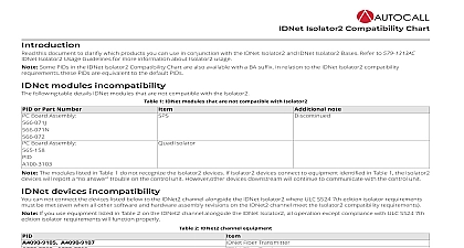
IDNet Isolator2 Usage Guidelines Isolator2 safely isolates a channel in the event of a wiring fault and monitors the wiring for restoration to normal when the fault is repaired is possible to configure systems using Class A wiring Class A with zone isolations DCLC or Class X wiring that meets NFPA 72 or ULC S524 using the Isolator2 See the Wiring section for more instructions usage guidelines feature information on the following Isolator2 type devices A4090 9122 IDNet Isolator2 A4098 9767E A4098 9767BA A4098 9766 A4098 9767 IDNet Isolator2 Bases Isolator2 features the following benefits over existing technologies Self restoration when fault is repaired No impact on required operation times of the Fire Alarm Control Unit FACU to a fire per agency standards following a wiring fault circuit internal isolation switch in the Isolator2 separates shorted and or disabled wiring from functioning wiring to optimize the available appliances The communicates the module status to the control panel so you can identify the shorted wiring location a complete list of compatible devices and minimum requirements refer to 579 1324AC IDNet Isolator2 Compatibility Chart and AC4090 0011 IDNet Addressable Devices Device Communications Compatibility Chart Module Isolator2 type can only be used on IDNet2 based Modules They do not function nor are they recognized on prior revisions of IDNet IDNet or requirements Isolator2 requires the following firmware 4010ES or 4100ES software revision 6.01 or higher 4007ES software revision 6.01 or higher or IDNet2 2 firmware revision 3.01 or higher IDNet Isolators if you can use the Isolator2 with existing addressable IDNet Isolators A4090 9116 and IDNet Isolator Bases A4098 9777 A4098 9793 mixing isolators with Isolator2 does not meet ULC S524 7th edition In this mixed fire alarm system all the Isolator2 performance improvements are present see Performance improvements For explicit limitations when mixing types see Appendix A Wiring examples Isolator and Isolator2 devices are present on your IDNet2 channel follow the strictest requirements from the two installation manuals 1 IDNet Isloator2 and legacy isolator instruction manuals Isolators Isolator Base If at least one IDNet Isolator Base A4098 9777 A4098 9793 or one Addressable IDNet Isolator A4090 9116 is present on the IDNet channel maximum line resistance between the FACU and the isolator and between any two isolators is 10 ohms 780 ft 18 AWG See Figure 1 for an of a correct application instructions 574 707AC for both Isolator and Isolator2 bases Isolators instructions Rev A Isolator2 Usage Guidelines 1 Maximum wire length between isolators is 10 ohm if a 4090 9116 4098 9777 or 4098 9793 isolator is installed wiring can wire Isolator2 isolators in any direction and you can connect input on either P1 or P2 The direction has no impact on recovery time or there are remote isolators or isolator bases on the loops it is recommended to address the isolators in ascending order start from the B side and each successive isolator a higher address than the isolator it precedes Isolation functionality is not affected by the order of isolator addresses there is at least one prior remote isolator A4090 9116 or one prior isolator base A4098 9777 A4098 9793 on the channel addressing the as recommended speeds up the system power up any time the IDNet2 is reset there are only Isolator2 A4090 9122 or Isolator2 bases A4098 9766 A4098 9767 on the channel addressing the isolators as speeds up the Earth Fault Search diagnostic tool can set the address of regular IDNet devices devices that are not isolators A4090 9116 A4090 9122 A4098 9777 A4098 9793 A4098 9766 in any order without impact 2 Rev A Isolator2 Usage Guidelines This is the preferred method as isolators are addressed in ascending order through the branches from the B side Non isolators devices be addressed in any way 2 Correct addressing 3 Incorrect addressing This is not the preferred addressing because isolators are not addressed in ascending order example shows 100 50 1 this will take time variable to complete the automatic Earth Fault Diagnostic Isolators 2 lists the IDNet Isolator2 type their address and the unit load draw on an IDNet2 line 2 IDNet Isolator2 infomation at least one Isolator2 type isolator is present on the channel you can configure a maximum of 50 isolator addresses for each IDNet2 channel the following table for the address count of different devices Isolator2 Isolator2 Base A4098 9767 A4098 9793 3 load 3 Isolator address count Isolator2 Isolator2 Base IDNet Isolator Isolator Base address count of 50 per IDNet2 channel Rev A Isolator2 Usage Guidelines 4 Counting the maximum number of Isolator2 per IDNet2 channel devices module specifies the maximum number of devices on an IDNet channel Isolator2 are used a maximum of 50 IDNet unit loads can be installed adjacent to an Isolator2 Some IDNet devices take more than one unit load as specified in their installation manual and in the AC4090 0011 IDNet and Addressable Devices Communications Compatibility Chart The usual total maximum IDNet devices and unit loads per channel remain 4 Rev A Isolator2 Usage Guidelines 5 Counting the maximum unit loads between Isolator2 improvements Isolator2 features several performance improvements when compared to prior isolators Time Isolator2 features a significant improvement to the recovery time of a system during a wiring fault If all of the channel isolators are of the type only and if they are installed to maximize performance an open fault a short circuit fault or a ground fault in one fire alarm zone will no distinctive impact on devices in other zones When faulting a zone if the wiring class allows it you should expect no missing or failed devices you should expect no additional delay in the response from initiating devices in other zones Fault Search earth fault search time depends on the installed devices The time to solution varies according to the number of isolators per loops as well as the scheme The search time is dependent on the distance between the earth fault and the FACU The maximum expected time on a Class A loop 50 isolators and where the earth fault is after the last device is less than six minutes The TrueStart Instrument TSI II can take up to 13 minutes in case situations time the the Isolator2 the IDNet2 channel is operational initiating devices able to report a fire quicker than with prior isolators on system power up improved time is also noticeable when a long standing wiring fault clears and the system is brought back to normal operation any Class A B or X style wiring configuration with more than one IDNet loop it is recommended that the Isolator2 is the first and last device A and X all used loops in order to meet Isolator2 performance on the channel See the wiring notes for each style for further information B DCLB 5 Rev A Isolator2 Usage Guidelines 6 Preferred Class B wiring two loops 7 Preferred Class B wiring one loop a short circuit fault is adjacent to a FACU before the first Isolator2 the fault will momentarily deactivate the different loops on the channel it resolves the issue This takes less than 10 seconds After recovery the initiating devices need to be reconfigured which can take more 10 seconds the momentary delay is not acceptable such as for meeting ULC S524 7th edition ensure that short circuit faults can not be created on FACU direct output One way of achieving this is by placing the Isolator2 close nippled to the FACU The Isolator2 reacts quicker than the to preserve other zones and other loops of a same IDNet2 channel Other solutions may exist consult with your local authority having AHJ isolators should be Isolator2 If one isolator is a prior isolator A4090 9116 A4098 9777 A4098 9793 the loop open fault will not meet S524 7th edition and a short circuit will momentarily affect all loops on the IDNet2 channel Mixing isolator types is not recommended A DCLA Class A the presence and placement of the isolators depends on the application 6 Rev A Isolator2 Usage Guidelines 8 Correct Class A wiring a Class A circuit you do not require an Isolator2 if there is only one IDNet loop See note 3 when using more than one loop