Autocall Modules A006-9803 Relay Module Installation Manual

File Preview
Click below to download for free
Click below to download for free
File Data
| Name | autocall-modules-a006-9803-relay-module-installation-manual-0643725918.pdf |
|---|---|
| Type | |
| Size | 785.97 KB |
| Downloads |
Text Preview
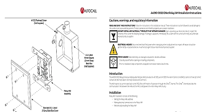
A006 9803 Relay Module Installation Instructions Warnings and Regulatory Information AND SAVE THESE INSTRUCTIONS Follow the instructions in this installation manual These instructions must be followed to avoid damage to product and associated equipment Product operation and reliability depend upon proper installation NOT INSTALL ANY AUTOCALL PRODUCT THAT APPEARS DAMAGED Upon unpacking your Autocall product inspect the contents of the for shipping damage If damage is apparent immediately file a claim with the carrier and notify an authorized Autocall product supplier HAZARD Disconnect electrical field power when making any internal adjustments or repairs All repairs should be performed by a or an authorized agent of your local Autocall product supplier HAZARD Static electricity can damage components Handle as follows Ground yourself before opening or installing components Prior to installation keep components wrapped in anti static material at all times publication describes installing and wiring the A006 9803 Expansion Relay Module This module provides ten programmable relays 1 identifies the mounting location for the Expansion Relay Module on the Main System Board MSB 1 Power specifications 24 VDC mA plus 10 mA for each energized relay 2 Environmental specifications for indoor installation in typical commercial environment to 120 0 to 49 to 90 Relative Humidity from 32 to 100 0 to 38 1 Location of A006 9803 Relay Module Rev A SYSTEM BOARD CONVENTIONAL12345678910Expansion Relay Modulefirealarmresources com Relay Module Installation Instructions the Expansion Relay Module the Expansion Relay Module is a four step process Refer to the following sections for specific information about performing these steps the LCD Display Keypad to gain access to the Expansion Relay Module mounting location the mounting bar to the Main System Board standoffs to the MSB and secure the Expansion Relay Module to the mounting bar and to the MSB the LCD Display Keypad the LCD Display Keypad LCD Display Keypad mounts to the MSB using three T15 Torx screws Remove these three screws Refer to Figure 2 for the location of screws Disconnect the harness running from the keypad to the MSB at the MSB the LCD assembly away from the MSB Pay attention to the header and connector that attach the LCD to the MSB making sure not to the header pins 2 Mounting expansion relay Mounting Bar mounting bar attaches to the metal posts located on each side of the MSB the end of the mounting bar with the tab into the slot on the left post the end of the bar with the round hole over the threaded portion of the right post Use the nut included with the stabilizing bar to the bar to the right post See Figure 2 2 Rev A ScrewMountingScrewMountingScrewBarMounting firealarmresources com Relay Module Installation Instructions Expansion Relay Module to MSB two standoffs to the MSB in the locations shown in Figure 2 two dual sided headers 532 624 into connectors J1 and J2 on the Expansion Relay Module the holes on the bottom corners of the Expansion Relay Module with the standoffs the header pins on the Expansion Relay Module with the connectors J4 and J5 on the panel main system board Align the standoff on the Expansion Relay Module with the standoffs mounted on the MSB press down on the Expansion Relay Module making sure that the header pins and standoffs are aligned Relays wiring to the panel and its peripherals must be performed in accordance with NFPA 70 NFPA 72 all local codes and per the technical requirements in each section below guidelines Use a voltmeter VOM to verify no stray voltages are applied to the field wiring Test for AC and DC voltages across each pair of wires and from wire to earth Use a VOM to verify that all wiring tests free of grounds Each conductor should test open against earth chassis All wiring must be 18 AWG minimum to 12 AWG maximum Contact rating 2A 30VDC pilot duty 35 power factor Each relay is selected for normally closed or normally open operation Shunt jumper setting see Figure 3 selects desired contact 3 Wiring relays 3 Rev A OPEN Jumper Left NORMALLY CLOSED Jumper Right RRRRRRRRRRRRRRRRRRRRJUMPERS TO SELECT NORMALLYOPEN OR CLOSED RELAY CONTACTS ONE JUMPER PER RELAY JUMPERCENTERRLY1RLY2RLY3RLY4RLY5RLY6RLY7RLY8RLY9RLY10firealarmresources com 2017 Johnson Controls All rights reserved All specifications and other information shown were current as of document revision and are subject to change without notice Additional listings may be applicable contact your local Autocall supplier for the latest status Listings and approvals under Tyco Fire Security GmbH and the product names listed in this material are marks and or registered marks Unauthorized use is strictly prohibited NFPA 72 and National Alarm Code are registered trademarks of the National Fire Protection Association NFPA Rev A