Autocall Multi-Candela Audible Visible (A V) Appliances; Ceiling Mount

File Preview
Click below to download for free
Click below to download for free
File Data
| Name | autocall-multi-candela-audible-visible-a-v-appliances-ceiling-mount-5964830712.pdf |
|---|---|
| Type | |
| Size | 4.85 MB |
| Downloads |
Text Preview
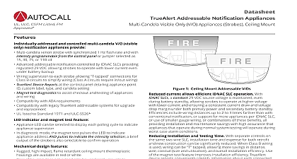
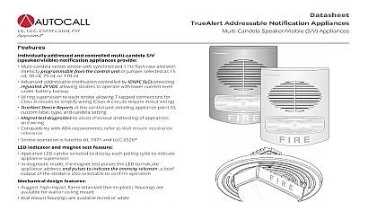
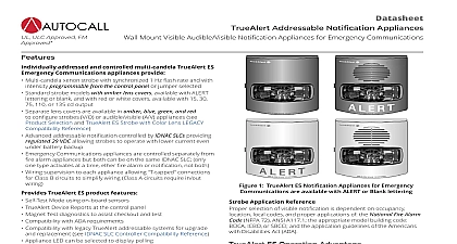
Datasheet Addressable Notification Appliances Audible Visible A V Appliances Ceiling Mount notification appliance horn Low current electronic horn with harmonically rich output sound for coded or steady operation Horns sound as Temporal or March Time pattern 60 or 120 BPM or continuously controlled separately from visible appliances on the two wire circuit Output is high or low 5 dBA difference IDNAC SLC control selects per device TrueAlert addressable A Vs provide convenient to standard electrical boxes Operation is individually and individually controlled with power supervision and supplied from a Autocall fire alarm control panel providing IDNAC Line Circuits SLCs Application Reference selection of visible notification is dependent on occupancy local codes and proper applications of the National Fire Alarm Signaling Code NFPA 72 ANSI A117.1 the appropriate model code BOCA ICBO or SBCCI and the application guidelines of Americans with Disabilities Act ADA SLC Operation Advantage A V Addressable Appliances on IDNAC SLCs provide and visible notification using a single two wire circuit that also connection to the individual notification appliance electronic This operation increases circuit supervision integrity by providing that extends beyond the appliance wiring connections current allows efficient IDNAC SLC operation With SLCs a constant 29 VDC source voltage is maintained even battery standby allowing strobes to operate at higher voltage lower current and ensuring a consistent current draw and voltage margin under both primary power and secondary battery standby include wiring distances up to 2 to 3 times farther than with notification or support for more appliances per IDNAC SLC use of smaller gauge wiring or combinations of these benefits all installation and maintenance savings with high assurance that that operate during normal system testing will operate during case alarm conditions Installation and Testing Time With separate controls on same two wire SLC installation time and expense for both retrofit new construction can be significantly reduced When Class B wiring used wiring can be T tapped allowing more savings in distance conduit size and utilization and overall installation efficiency Use the magnet test feature improves installation efficiency TrueAlert reports conveniently identify information about each connected Addressable Wiring Isolator Model A4905 9929 is available for remote mounting on addressable circuits to isolate short circuited wiring from wiring Refer to data sheet AC4905 0001 for additional ULC CSFM Listed FM 1 Mount Addressable A Vs addressed and controlled multi candela A V notification appliances provide Multi candela xenon strobe with synchronized 1 Hz flash rate and with programmable from the control panel or jumper selected as 30 75 or 110 cd Advanced addressable notification controlled by IDNAC SLCs providing 29 VDC allowing strobes to operate with lower current even battery backup Wiring supervision to each strobe allowing T tapped connections for B circuits to simplify wiring Class A circuits require in out wiring TrueAlert Device Reports at the control panel detailing appliance point custom label type and candela setting Magnet test diagnostics to assist checkout and testing of appliances wiring Compatibility with ADA requirements Compatibility with legacy TrueAlert addressable systems for upgrade replacement see TrueAlert Strobe LEGACY Compatibility Strobe operation listed to UL Standard 1971 and ULC Standard S526 Horn operation listed to UL Standard 464 and ULC Standard S525 indicator and magnet test feature Appliance LED can be selected to display each polling cycle to indicate supervision In diagnostic mode the magnet test pulses the LED to indicate address AND pulses to indicate the intensity selection a output of the strobe and the horn is also selectable to confirm design features Rugged high impact flame retardant thermoplastic housings are in red or white electrical boxes electrical boxes Rear of housing does not extend into box and easily mounts to Mounting options include red wire guards and adapters for surface This product has been approved by the California State Fire Marshal CSFM pursuant to Section 13144.1 of the California Health and Safety Code See CSFM Listings 7125 2269 0528 and for allowable values and or conditions concerning material presented in this document Additional listings may be applicable contact your local product supplier for the latest status Rev 6 03 2021 Audible Visible A V Appliances Ceiling Mount Addressable Diagnostics Features Controllers can be selected to pulse each appliance LED when it receives a supervision poll When the controller is selected for mode the appliance magnet test feature provides a response at the individual appliance being tested Appliance Magnet Test In this test mode in response to the magnet test the appliance LED pulses sequentially to conveniently indicate the address Appliance Testing In this test mode after the address is indicated by pulsing the appliance LED the strobe will briefly flash and the will briefly sound to indicate proper operation Instrument Two TSIT The 2nd generation of the Autocall TrueStart Test Instrument adds testing of IDNAC SLC wiring and TrueAlert and ES appliances to its ability to test IDCs NACs and IDNet communications before connection to the control panel Please contact your local representative for additional information Selection 1 Multi Candela Ceiling Mount Addressable A Vs Horn with Multi Candela Strobe intensity as 15 30 75 or 110 candela L x 6 W x 2 D 121 mm x 175 x 67 mm 2 Wire Guards and Ceiling Mount A V Adapter Wire Guard for mounting to flush mounted electrical box UL listed by Space Age Electronics Inc Adapter Plate required for surface mount guard Mount Adapter Box Extension use to cover 1 1 2 deep surface boxes x 6 x 3 216 mm x 156 mm x 76 x 7 229 mm x 178 mm x 6 x 1 deep 121 mm x 175 x 38 mm Mount A V and Guard Installation Reference 2 Mount A V and Guard Installation Reference Figure 2 features a A4905 9915 white A4905 9916 red adapter 4905 9927 red wire guard and a 4905 9928 adapter plate SLC Controller Compatibility Reference 3 IDNAC SLC Controller Compatibility Reference Controllers with EPS or EPS Power Supply IDNAC Repeater with IDNAC Notification with ESS Enhanced System Supply Sheet Output SLC Output Voltage Reference SLC VDC regulated VDC 6 VDC drop 2 Rev 6 03 2021 Audible Visible A V Appliances Ceiling Mount 4 General Specifications to 122 F 0 to 50 C 10 to 93 non condensing at 100 F 38 C blocks for 18 AWG to 12 AWG 0.82 mm2 to 3.31 mm2 two wires per terminal for wiring Instructions 579 808AC 5 Electrical Specifications Operating Voltage Range Requirements Rate and Synchronized SLC Loading Setting Output Selection VDC RMS Current Ratings for connection to Addressable SLCs horn steady on VDC to 31 VDC Special Application see page 4 for 17 VDC rating unit load 0.8 mA control panel current Hz with up to 46 synchronized strobes maximum per NAC cd mA cd mA cd mA mA mA m A cd mA mA Output Characteristics Output Ratings 10 ft 3 m 6 Horn Output to 3700 Hz sweep modulated at 120 Hz rate Type see UL 464 Test Chamber dBA dBA dBA dBA dBA dBA dBA dBA Coded horn values are ty