Autocall TrueAlert Addressable Isolator+ Module, Model A4905-9929

File Preview
Click below to download for free
Click below to download for free
File Data
| Name | autocall-truealert-addressable-isolator-module-model-a4905-9929-8590213746.pdf |
|---|---|
| Type | |
| Size | 1.91 MB |
| Downloads |
Text Preview
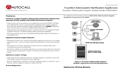
UL ULC CSFM Listed Addressable Notification Appliances Addressable Isolator Module Model A4905 9929 modules provide short circuit isolation for TrueAlert notification appliance wiring Power and communications are supplied by Autocall 4100ES 4010ES 4007ES fire alarm control panels equipped with power supplies provide advanced addressable notification from IDNAC Signaling Circuits SLCs and from 4009 IDNAC Repeaters Operation is also compatible with legacy TrueAlert SLCs from TrueAlert Supplies TPS or TrueAlert Addressable Controllers 4009T Dual port design accepts communications and power from either port automatically isolates one port from the other when a short circuit Mounts in standard 4 102 mm square electrical box 2 54 mm UL listed to Standard 864 diagnostics On board yellow LED provides module status can indicate poll or be activated from panel Isolators report faults to the host control panel method varies with connection type received at the control panel allows identification of short circuit location Autocall control panels providing IDNAC SLCs will be advised of appliances disabled due to activated isolators Other control panels controlling TrueAlert Addressable Controllers do recognize appliance addresses but will receive a report of an open channel trouble due to activated isolators B Style 4 IDNAC SLC wiring Up to 12 Isolator modules can be connected per IDNAC SLC and up 6 Isolator modules can be connected directly together in series on same branch A Style 6 IDNAC SLC wiring For Class A operation up to 6 Isolator modules can be connected per loop channel loading rules Isolator modules require one address and are rated as 4 unit loads TrueAlert addressable notification appliances are a single unit load Use of TrueAlert in this document refers to both TrueAlert and ES notification appliances Use of IDNAC SLCs also refers to of TrueAlert SLCs 1 TrueAlert Isolator Module One Line Drawing Including Module Detail Addressable Notification SLCs and legacy TrueAlert SLCs are isolated from each other In the event of a channel wiring short the channel will safely shut down and then monitor the wiring for to normal when the short is repaired However within the and T tap wiring of an IDNAC channel the use of A4905 9929 Isolator Modules can provide additional isolation that can the quantity of TrueAlert addressable appliances impacted by a circuit Circuit Isolation An internal isolation relay allows the Isolator module to separate shorted and or disabled wiring from functioning to optimize the available appliances Isolator module status is to the control panel providing assistance in identifying shorted wiring location Location The A4905 9929 Isolator Module mounts in standard 4 square 2 deep electrical box allowing isolators to be located on the IDNAC SLC channel where the local wiring most benefit This product has been approved by the California State Fire Marshal CSFM pursuant to Section 13144.1 of the California Health and Safety Code See CSFM Listing 7300 2269 0553 for allowable and or conditions concerning material presented in this document Additional listings may be applicable contact your local product supplier for the latest status Rev 8 01 2020 Addressable Isolator Module Model A4905 9929 Isolator Example 1 Protection The diagram below illustrates the addition of A4905 9929 Isolator Modules to IDNAC SLC wiring located at the start of each With Isolator modules added in these locations there will be an increase in overall system operation in the event of a short circuit Short Circuits Without Isolator modules if a short circuit occurred on a branch connection the entire channel would be inoperative the as occurs with conventional Notification Appliance Circuit NAC operation With the addition of Isolator modules short circuits would only those appliances connected electrically beyond the Isolator module Since short circuits are sometimes encountered during initial wiring the use of Isolator modules can also assist in finding those wiring faults allowing a decrease in the total installation and checkout time Allocation For the example shown below there are 18 notification appliances which would occupy a total of 18 addresses at the 4100ES panel There are also 4 Isolator modules each requiring an address The total addresses count on this IDNAC SLC would be 18 4 22 Loading Isolator modules are powered from the IDNAC SLC and they require an additional loading factor with each Isolator designated as four loads Each TrueAlert addressable appliance whether strobe horn or combination unit is only one address and only one unit load The total unit for this example is 18 appliances 4 Isolator modules 4 unit loads each 18 16 34 unit loads Capacity Capacity may vary with IDNAC SLC control but typically is up to 127 addresses and up to 139 unit loads This example is not fully and could probably accommodate additional appliances However the appliance currents also need to be considered IDNAC SLCs and legacy SLCs are rated 3 A full load TrueAlert Addressable Controller channels are rated 2.5 A full load Isolator Example 1 One Line Diagram Showing Individual Branch Protection 2 Rev 8 01 2020 Addressable Isolator Module Model A4905 9929 Isolator Example 2 Isolator Example 3 Tap Level Isolation The one line diagram directly below shows Isolator modules located at the start of each T tap on a single branch of a IDNAC SLC all wired Class B Style 4 With this approach each tap is isolated from short circuits that may occur out on the other taps Loading Total addresses 15 Total unit loads 11 appliances 4 Isolator modules 4 unit loads each 11 16 27 unit loads A Wiring Isolation Example 3 at the bottom of this page illustrates an optimized Class A Style 6 IDNAC SLC with each notification appliance between an Isolator module With this connection a single short circuit between Isolator modules would only disable one TrueAlert appliance Please note that Isolator modules can be applied as desired the configuration shown is to illustrate operation and is not Loading Total addresses 11 Total unit loads 5 appliances 6 Isolator modules 4 units loads each 5 24 29 unit loads Isolator Example 2 One Line Diagram Showing Individual T Tap Protection Isolator Example 3 One Line Diagram Showing Class A Style 6 with Isolators 3 Rev 8 01 2020 Isolator Mounting Information Addressable Isolator Module Model A4905 9929 4 Rev 8 01 2020 Circuit Wire Resistance Range Isolated Mode Requirements Load Requirements B A Material Plate Material Range Range Connections Instructions Addressable Isolator Module Model A4905 9929 1 Electrical maximum measured from any Isolator port to the farthest appliance in the protected to 32 VDC provided from TrueAlert channel mA 24 VDC Address per Isolator Module Unit loads per Isolator Module 1 unit load 0.8 mA control panel current 2 IDNAC SLC Loading to 12 Isolator modules total with up to 6 being connected directly together in series on the branch to 6 Isolator modules total on the loop 3 Mechanical H x 4 W x 1 D 105 mm x 105 mm x 35 mm thermoplastic metal galvanized to 120 F 0 to 49 C intended for indoor operation to 93 RH at 100 F 38 C terminals for 18 to 12 AWG 0.82 mm2 to 3.31 mm2 4 Reference Data with IDNAC SLCs IDNAC Repeater with ESS with EPS with ES PS 5 Rev 8 01 2020 Addressable Isolator Module Model A4905 9929 2020 Johnson Controls All rights reserved All specifications and other information shown were current as of document revision and are subject to change without notice listings may be applicable contact your local Autocall product supplier for the latest status Listings and approvals under Tyco Fire Security GmbH and the names listed in this material are marks and or registered marks Unauthorized use is strictly prohibited NFPA 72 and National Fire Alarm Code are registered of the National Fire Protection Association NFPA