Autocall TrueAlert ES Addressable Speakers Weather Proof Installation Manual

File Preview
Click below to download for free
Click below to download for free
File Data
| Name | autocall-truealert-es-addressable-speakers-weather-proof-installation-manual-8534162709.pdf |
|---|---|
| Type | |
| Size | 5.09 MB |
| Downloads |
Text Preview
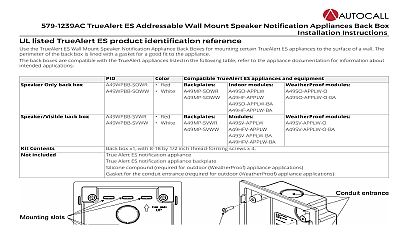
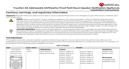
TrueAlert ES Addressable US Weather Proof Ceiling Mount Speaker Notification Appliances Instructions warnings and regulatory information When the notification appliance emits light or sound it indicates the possibility of an emergency situation that requires immediate atten of all occupants Always install maintain and test notification appliances within their specifications Failure to follow all safety precautions instructions may result in loss of life and property due to non functioning notification appliances Some notification appliances high voltage To avoid electrical hazards and avoid damage to appliances make sure that the electrical power for the Notification Circuit is disconnected at the control unit before installing repairing or internally adjusting any notification appliances Even electrical power removed some notification appliances such as visible strobes store a high voltage charge The high voltage can injury resulting in death from electrical shock DO NOT TOUCH EXPOSED CIRCUITRY REFERENCE Location and quantity of appliances required must conform to the applicable local standards and guidelines National Fire Alarm and Signaling Code NFPA 72 ULC Standard CAN ULC S524 Installation of Fire Alarm Systems the appropriate building codes and specific requirements of the local Authority Having Jurisdiction AHJ These notification appliances are not for installation within hazardous locations as defined by the National Electrical Code NEC or NFPA listed TrueAlert ES indoor product identification reference 1 Product Identification Reference Red White S V cover Red White boxes boxes appliances provide an SO or audible visible S warning of an alarm condition activated from the control of a compatible UL Listed Autocall Fire Alarm Consult Autocall Fire panel documentation for information The can be turned ON OFF under compatible control SO cover contents included For information about TrueAlert ES appliance testing consult TrueAlert ES Addressable Appliances Troubleshooting 579 1049AC operation levels A49 S V appliances have multiple strobe intensity levels Levels W135 W110 and W185 are rated for UL outdoor private mode applications Level is rated for UL indoor and uncontrolled wet Public Mode applications x 1 with 1.25 in 8 16 thread forming screws x 4 a back box to mount the appliance assembly to the ceiling Order a cover for each appliance Rev B ES Addressable US Weather Proof Ceiling Mount Speaker Notification Appliances Installation instructions Select the mounting location and install the back box using screws suitable for the mounting surface Connect the building wires to the terminals at the back of the appliance see the wiring section Secure the appliance to the back box using the provided hardware Set the appliance settings See Setting the address DIP switch Attach the cover to the appliance For the A49SO align the cover mounting tab with the tab in the backbox and carefully place the cover onto unit For the A49SVH align the cover mounting tab with the strobe dome and carefully place the cover over the unit Press the cover until it snaps into place instructions Make sure that all power is disconnected before starting the installation 3 instructions ensure proper continuity use a torque wrench to tighten the terminal block screws to 12 to 15 lb in At the back box connect the building wiring to the CKT and CKT terminals on the appliance Ensure that the correct polarity is maintained for each strobe unit SLC wiring must be twisted pair TWP CKT Terminals accept two wires 12 to 18 American wire gauge AWG TWP Strip the lead insulation to 7 16 in maximum 2 Rev B 4 instructions ES Addressable US Weather Proof Ceiling Mount Speaker Notification Appliances Installation notes Assign a maximum of 127 active appliances to a circuit Assign a maximum of 12 active strobe appliances to a powered circuit The maximum resistance between appliances is 25 ohms Refer to the Field Wiring Diagrams of the driving compatible fire alarm control panel for instructions Notification appliances are rated using an individual module label Maintain the correct polarity on the terminal connections 1 through 6 each accommodate two wires one wire going in and one wire going out to the next appliance appliances are rated to the operating voltage limits of 23 VDC to 30 VDC The appliance can fail to operate as intended and can cause damage to this equipment if it operates outside of these limits Only operate the TrueAlert IDNAC S V and SO using a compatible power supply and amplifier is not permitted for Class A wiring SLC wiring connections are supervised and power limited the address DIP switch addressable TrueAlert IDNAC notification appliance has a unique address that is set using an eight position DIP switch ADDR1 up to 127 unique addresses an signaling line circuit SLC however the total appliance loading available may be less due to appliance current set the address complete the following steps Unclip the cover from the appliance by inserting a slotted screwdriver or a similar sized object into the opening at either end of the cover Figure 5 Use a non metallic stylus or the equivalent to set the switches Record the set address DIP switch position 8 determines whether this appliance is viewed by the system as an ALARM OFF or ALERT ON type of appliance the setting for the appliance at this address with the FACP system configuration documentation 5 the DIP switch address the strobe candela setting The jumpers are factory set to FACP Use this setting when programming the candela setting at the 4100ES FACP The candela setting is visible the slot on the side of the appliance For manual selection remove the cover and slide the candela flag to the required setting W75 W110 W185 110 candela or FACP candela setting is visible through the slot on the side of the appliance To avoid a programming mismatch trouble an authorized service personnel must program one of the four candela outputs for each appliance set the candela through the Programmer set it to FACP For additional information refer to the 4100ES Programmer Manual 574 849AC 3 Rev B ES Addressable US Weather Proof Ceiling Mount Speaker Notification Appliances Installation circuit configuration for S V and SO appliances the wire harness position to the correct terminal post for audio circuit voltage and power tap selection See Figure 6 and Table 4 jumper at P2 on the speaker transformer drive board at the rear of the unit is factory set to 1 2 for a 25V 1 4W output For a 70V 2W output set jumper to 2 3 see Figure 6 Use the default setting 1 2 for all other speaker tap settings 6 the strobe and appliance configuration specifications 2 Environmental specifications APPLICATION 23 VDC to 30 VDC to 151 40 to 66 DC Control Strobe Voltage Range temperature rating CD W135 CD W185 CD temperature rating for and uncontrolled wet Public Mode 110 CD temperature rating humidity range The appliance covers and backboxes are available in red and white Do not paint or otherwise alter the factory finishes in any way to 120 40 to 50 non condensing at 60 60 for 18 AWG to 12 AWG 0.82 mm2 to 3.31 mm2 to 120 0 to 49 Only voltage mA mA 3 Maximum RMS operating current 4 Speaker Specifications mA mA mA VRMS or 70.7 VRMS are for connection to compatible fire alarm audio circuits W 1 2 W 1 W and 2 W Hz to 4000 Hz taps using Jumper J1 response Alarm 5 Vertical and horizontal light dispersion rat