DSC AMB-500 - Installation Manual - English - Addressable Bravo 5 Ceiling-Mount Passive Infrared Detector

File Preview
Click below to download for free
Click below to download for free
File Data
| Name | dsc-amb-500-installation-manual-english-addressable-bravo-5-ceiling-mount-passive-infrared-detector-4061238795.pdf |
|---|---|
| Type | |
| Size | 639.17 KB |
| Downloads |
Text Preview
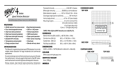
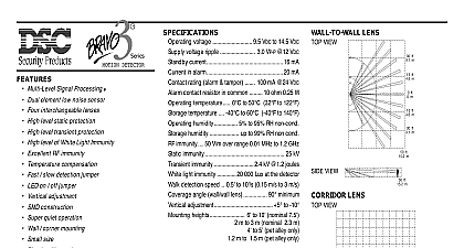
AMB 500 PIR Detector INSTRUCTIONS AMB 500 is a ceiling mount detector designed to provide reliable motion for residential and commercial applications The AMB 500 uses a special lens made for 360 detection in conjunction with a quad element PIR sensor for uniform detection all around its field of view Special attention is given to alarm immunity against RF static electrical transient to ensure trouble free for many years AMB 500 uses a 2 wire connection for power and to communicate with the control This simplifies wiring and reduces installation cost The AMB 500 low current also maximizes the number of devices that can be attached to an addressable loop Protected by one or more of the following patents Canada 2099971 US 5444432 Rating 75 mA standby 3 mA test mode Environment 0 32 5 95 RH non condensing RF immunity 10 V m with 80 AM over range 80MHz to 1.0GHz RF immunity 10V with 80 AM over range 150kHz to 100MHz immunity 15 kV immunity 2.4 kV 1.2 joules detection range diameter placed 8 ft 2.4 m from floor 24 ft 7.3 m placed 10 ft 3.0 m from floor 30 ft 9.2 m placed 12 ft 3.6 m from floor 40 ft 12.2 m detection speed 0.5 10 s 0.15 3m s switch contact rating 0.1A 24VDC Panel Compatibility PC4010 4020 v3 x PC5010 PC5015 v2 x with interface module COMPLIANCE STATEMENT Changes or modifications not expressly approved by Digital Security Controls Ltd could void your to use this equipment equipment generates and uses radio frequency energy and if not installed and used properly in strict accordance the manufacturer instructions may cause interference to radio and television reception It has been type tested and to comply with the limits for Class B device in accordance with the specifications in Subpart of Part 15 of Rules which are designed to provide reasonable protection against such interference in any residential installation there is no guarantee that interference will not occur in a particular installation If this equipment does cause to television or radio reception which can be determined by turning the equipment off and on the user is to try to correct the interference by one or more of the following measures Re orient the receiving antenna Relocate the alarm control with respect to the receiver Move the alarm control away from the receiver Connect the alarm control into a different outlet so that alarm control and receiver are on different circuits necessary the user should consult the dealer or an experienced radio television technician for additional The user may find the following booklet prepared by the FCC helpful to Identify and Radio Television Interference Problems This booklet is available from the U S Government Printing Washington D C 20402 Stock 004 000 00345 4 Warranty Security Controls Ltd warrants that for a period of five years from the date of purchase the product shall be of defects in materials and workmanship under normal use and that in fulfilment of any breach of such warranty Security Controls Ltd shall at its option repair or replace the defective equipment upon return of the to its repair depot This warranty applies only to defects in parts and workmanship and not to damage in shipping or handling or damage due to causes beyond the control of Digital Security Controls Ltd such lightning excessive voltage mechanical shock water damage or damage arising out of abuse alteration or application of the equipment foregoing warranty shall apply only to the original buyer and is and shall be in lieu of any and all other warranties expressed or implied and of all other obligations or liabilities on the part of Digital Security Controls Ltd Digital Controls Ltd neither assumes nor authorizes any other person purporting to act on its behalf to modify or to this warranty nor to assume for it any other warranty or liability concerning this product no event shall Digital Security Controls Ltd be liable for any direct indirect or consequential damages loss of profits loss of time or any other losses incurred by the buyer in connection with the purchase installation or or failure of this product detectors can only detect motion within the designated areas as shown in their respective installation instruc They cannot discriminate between intruders and intended occupants Motion detectors do not provide volumetric protection They have multiple beams of detection and motion can only be detected in unobstructed areas covered these beams They cannot detect motion which occurs behind walls ceilings floor closed doors glass partitions doors or windows Any type of tampering whether intentional or unintentional such as masking painting or of any material on the lenses mirrors windows or any other part of the detection system will impair its proper infrared motion detectors operate by sensing changes in temperature However their effectiveness can be reduced the ambient temperature rises near or above body temperature or if there are intentional or unintentional sources of in or near the detection area Some of these heat sources could be heaters radiators stoves barbeques fireplaces steam vents lighting and so on Digital Security Controls Ltd recommends that the entire system be completely tested on a regular However despite frequent testing and due to but not limited to criminal tampering or electrical it is possible for this product to fail to perform as expected Information Changes or modifications not expressly approved by Digital Security Controls Ltd could void user authority to operate this equipment Digital Security Controls Ltd Canada www dscgrp com in Canada 29004861 R001 Patterns for AMB 500 the Detector a detector location that will provide the coverage required keeping in mind the potential problems Do not aim the detector at reflective surfaces such as mirrors or windows as this distort the coverage pattern or reflect sunlight directly onto the detector Avoid locations that are subject to direct high air flow such as near an air duct outlet Do not locate the detector near sources of moisture steam or oil Do not aim the detector such that it will receive direct or reflected mirror sunlight Do not limit the coverage by large obstructions within the detection area such as or filing cabinets Wiring connect the AMB 500 consult the wiring diagram below open the case gently twist the top cover counter clockwise and lift it up from the cover Use a small screwdriver to remove the appropriate knockouts for wiring the bottom cover using the screws supplied close the case use the locating line on the bottom cover to align the tab on the top Once the top cover is engaged twist the top cover clockwise to lock it in place Since no adjustment is necessary for the circuit board it is not recommended the installer remove the circuit board from the case Enrollment serial number located on the back of the device must be enrolled into the alarm panel via Installer Programming Q 8 Installer Code This procedure is for the PC4010 4020 in the control panel Installation Manual and for the panels in the PC5100 Installation Manual Connect only DSC Addressable Series devices to the addressable connections Connection of ANY other type of device will impair operation devices other than Addressable Series devices which require power to must be powered separately Testing the detector has been set up walk test the entire area where coverage is Should the coverage be incomplete readjust or relocate the detector to full coverage NOTE Upon installation the unit should be thoroughly tested to proper operation The end user should be instructed on how to perform tests and should walk test the detector weekly the sensitivity 500 features Fast and Slow detection modes which are set on jumperJ1 J1 is set at the factory