DSC AMP 704 IM EN NA

File Preview
Click below to download for free
Click below to download for free
File Data
| Name | dsc-amp-704-im-en-na-2917340568.pdf |
|---|---|
| Type | |
| Size | 816.14 KB |
| Downloads |
Text Preview
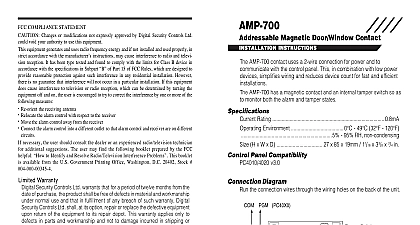
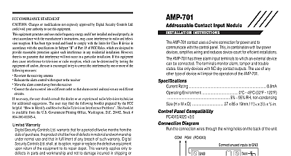
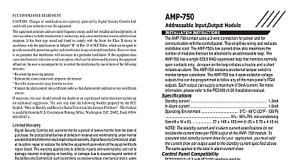
AMP 704 Interface Module INSTRUCTIONS 1 AMP 704 AMP 704 Point Interface Module PIM allows for the connection of non powered or ex powered hardwired devices to the Addressable Multiplex Loop AML The four in and cover tamper can be individually enrolled as zones on the control panel The is jumper selectable for either N C loops SEOL or DEOL resistors AMP 704 PIM uses a 2 wire connection for power and to communicate with the control This in combination with low power devices simplifies wiring and reduces installation The AMP 704 low current draw also maximizes the number of modules that can be to an addressable loop For additional information on AML wiring please refer to compatible panel Installation Manuals 12V Draw 3.4mA max Burg Config 6.7mA max Fire Config resistance 100 max loop response 400ms 32 120 F 0 49 C 0 93 non condensing Panel Compatibility PC4020 PC4020CF v3.0 and higher PC5010 v2.0 and higher PC5015 v2.2 and higher PC5020 PC5020CF v3.0 and higher PC5100 Addressable Expansion Module For Commercial Fire applications use the AMP 704 only in conjunction with models and PC5020CF control units a mounting location for the AMP 704 The module should be located in a dry location as close as possible to the points to be protected Alternatively to the method explained the PCB may be mounted in a metal cabinet using the standoffs provided with the refer to Figure 3 Remove the cover using a flat blade screwdriver to push in the tab at the bottom of the G N D Z 1 C O M Z2 Z3 C O M Z4 1 of the backplate Pull the addressable loop and input wires through the wiring access holes located at the Mount the device securely to the wall using the two mounting tabs on the backplate or the two mounting holes inside the backplate To use the holes inside the PCB must be removed To do this remove the 3 screws holding the PCB and lift it out When replacing the PCB do not over tighten the screws the PCB be damaged If the mounting tabs are not being used to mount the device they can be broken off Wire the module and configure the EOL supervision jumper as per the instructions below Replace the cover and insert the cover screw the AMP 704 wiring as indicated below Current vs Wiring Distance PC4020 PC5100 Loop mA AWG ft m AWG ft m 2 AMP 704 Wiring LIMITED PGM1 PGM2 STR AUX STR GND Z1 COM Z2 COM Z4 LIMITED to EOL supervision proper input connections 12V 1mA Connect only DSC addressable devices to the addressable loop Connection of any other type of device will impair operation Any other than addressable devices that require power to operate must be separately 3 Power Limited and Non Power Limited Wiring this diagram is representative of compatible control panels Panel Do not route any wiring circuit boards Maintain at least 25.4mm separation Limited Tie not provided prevent wires from falling onto batteries them to the enclosure or to the plastic located under the control panel fire installations come through connections BATTERY AC WIRING AS SHOWN A minimum 1 4 6.4mm separation must be main at all points between battery primary AC wiring and all other connections The AMP 704 is mounted inside the compatible unit enclosure using 3 nylon spacers 3 8 9.6mm Supervision Jumper CON1 Loops configuration allows the use of N C normally closed contacts on Multiple N C contacts can be wired in series NOTE This configu is not for UL installations use only with AMP 704 INT model is not UL Listed Zx C Zx Residential Burglary Applications End of Line SEOL default configuration allows the use of N C normally closed and or normally open contacts Use in conjunction with one 5.6K resistor DSC Model EOLR 2 Zx Zx Zx Commercial Burglary Applications End of Line DEOL resistors allow the zone to be monitored for tamper secure and violated conditions N C normally closed contacts can be used this configuration Use in conjuction with two end of line resistors DSC Model EOLR 2 Zx Zx Residential and Commercial Fire Applications software version 1.0F only End of Line SEOL Loops configuration allows the use of N O normally open contacts only Multiple N O can be wired in parallel Use in conjunction with one 2.2K end of line resis DSC Model EOLR 1 Inputs AMP 704 has a total of 5 serial numbers SNs one for the cover tamper and one for of the four inputs The serial numbers can be found on the inside of the front cover serial number can be enrolled individually into the control panel via Installer Program 8 Installer Code This procedure is outlined in the PC4020 Installation Manual in the PC5100 Installation Manual for PowerSeries panels The AMP 704 serial numbers do not need to be enrolled as consecutive zones in system Do not combine burglary and fire devices on the same loop module is shipped with a separate label pack with individual SN stickers that can be inserted into the Installation Manual for recording purposes If required the serial can be determined from the tamper serial number ROOT SN located on the circuit board This 5 digit number begins with the digit 2 and ends with the digits 0 5 The 4 input serial numbers are numbered in sequence from the tamper serial number example If the root serial number is 21230 then the serial number for inputs 1 through 4 be 21231 21232 21233 and 21234 Zx COMPLIANCE STATEMENT Changes or modifications not expressly approved by Digital Security Controls Ltd could void your authority use this equipment equipment generates and uses radio frequency energy and if not installed and used properly in strict accordance with manufacturer instructions may cause interference to radio and television reception It has been type tested and found comply with the limits for Class B device in accordance with the specifications in Subpart of Part 15 of FCC Rules are designed to provide reasonable protection against such interference in any residential installation However there no guarantee that interference will not occur in a particular installation If this equipment does cause interference to tele or radio reception which can be determined by turning the equipment off and on the user is encouraged to try to cor the interference by one or more of the following measures Re orient the receiving antenna Relocate the alarm control with respect to the receiver Move the alarm control away from the receiver Connect the alarm control into a different outlet so that alarm control and receiver are on different circuits necessary the user should consult the dealer or an experienced radio television technician for additional suggestions The may find the following booklet prepared by the FCC helpful to Identify and Resolve Radio Television Interfer Problems This booklet is available from the U S Government Printing Office Washington D C 20402 Stock Canada Class B digital apparatus meets all requirements of the Canadian interference causing equipment regulations appareil num de la Classe B respecte toutes les exigences de r sur le mat brouilleur du Canada Warranty warrants that for a period of one year from the date of purchase the product shall be free of defects in material and under normal use and that in fulfillment of any breach of such warranty DSC shall at its option repair or the defective equipment upon return of the equipment to its repair depot Th