DSC AMX 400 IS EN NA

File Preview
Click below to download for free
Click below to download for free
File Data
| Name | dsc-amx-400-is-en-na-9462305187.pdf |
|---|---|
| Type | |
| Size | 891.34 KB |
| Downloads |
Text Preview
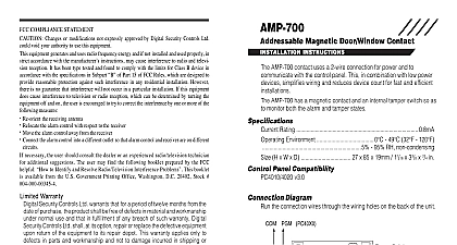
Table 2 AMX 400 Wire Run Chart Loop mA Loop Current mA AWG 1.02mm 22 AWG 0.635mm PC4020 PC5100 AWG 1.02mm 22 AWG 0.635mm Output 18 AWG recommended Wire run calculations include line loss and bat end of life operation Figure 1 AMX 400 Wiring Configuration Do not wire more than four AMX 400 modules in series from the source in series parallel configurations Warranty Security Controls Ltd warrants that for a period of 12 months from the date of purchase the product shall be free of defects in and workmanship under normal use and that in fulfilment of any breach of such warranty Digital Security Controls Ltd at its option repair or replace the defective equipment upon return of the equipment to its repair depot This warranty applies to defects in parts and workmanship and not to damage incurred in shipping or handling or damage due to causes beyond the of Digital Security Controls Ltd such as lightning excessive voltage mechanical shock water damage or damage arising out abuse alteration or improper application of the equipment foregoing warranty shall apply only to the original buyer and is and shall be in lieu of any and all other warranties whether or implied and of all other obligations or liabilities on the part of Digital Security Controls Ltd Digital Security Controls neither assumes responsibility for nor authorizes any other person purporting to act on its behalf to modify or to change this war nor to assume for it any other warranty or liability concerning this product no event shall DSC Ltd be liable for any direct indirect or consequential damages loss of anticipated profits loss of time or any losses incurred by the buyer in connection with the purchase installation or operation or failure of this product Digital Security Controls Ltd recommends that the entire system be completely tested on a regular basis However frequent testing and due to but not limited to criminal tampering or electrical disruption it is possible for this product to fail perform as expected INFORMATION Changes or modifications not expressly approved by Digital Security Controls Ltd could void the authority to operate this equipment Digital Security Controls Ltd Canada cid 127 www dsc com in Canada R002 Loop Regenerator Instructions AMX 400 Addressable Loop Regenerator can be connected to a PC4020 or PC5100 mod to extend the allowable wiring distance on the addressable loop The unit isolates addres devices limiting the effect of short circuits The AMX 400 can be powered from the power of the control panel or from an independent power supply A maximum of AMX 400 modules can be wired in series Operating Current 40mA plus current draw of addressable devices Supply Voltage 12VDC min CONTROL PANELS PC4020 v3.0 and higher PC5010 v2.0 and higher requires PC5100 PC5020 v3.1 and higher requires PC5100 to Figure 1 for wiring details and Table 2 for the wire run chart Select a location for the AMX 400 module Remove power from system Locate 3 mounting holes in cabinet that align with module mounting holes Insert stand in cabinet mounting holes and snap standoffs into place Align module mounting with standoffs and snap module into place Connect the 12VDC from the power supply to the RED terminal on the AMX 400 the ground wire from the power supply to the BLK terminal on the AMX 400 Connect the incoming addressable loop to the IN and IN terminals of the AMX 400 the correct polarity Connect the outgoing addressable loop to the OUT and OUT terminals of the observing the correct polarity Power up system and perform system test 1 Current Calculation Chart Device Draw standby mode Detector Motion Detector PIR PIR Detector Detector Door Window Contact Input Module Point Module Current Draw Maximum 170mA 2 AMX 400 Wire Run Chart Loop mA Loop Current mA AWG 1.02mm 22 AWG 0.635mm PC4020 PC5100 AWG 1.02mm 22 AWG 0.635mm Output 18 AWG recommended Wire run calculations include line loss and bat end of life operation Figure 1 AMX 400 Wiring Configuration Do not wire more than four AMX 400 modules in series from the source in series parallel configurations Warranty Security Controls Ltd warrants that for a period of 12 months from the date of purchase the product shall be free of defects in and workmanship under normal use and that in fulfilment of any breach of such warranty Digital Security Controls Ltd at its option repair or replace the defective equipment upon return of the equipment to its repair depot This warranty applies to defects in parts and workmanship and not to damage incurred in shipping or handling or damage due to causes beyond the of Digital Security Controls Ltd such as lightning excessive voltage mechanical shock water damage or damage arising out abuse alteration or improper application of the equipment foregoing warranty shall apply only to the original buyer and is and shall be in lieu of any and all other warranties whether or implied and of all other obligations or liabilities on the part of Digital Security Controls Ltd Digital Security Controls neither assumes responsibility for nor authorizes any other person purporting to act on its behalf to modify or to change this war nor to assume for it any other warranty or liability concerning this product no event shall DSC Ltd be liable for any direct indirect or consequential damages loss of anticipated profits loss of time or any losses incurred by the buyer in connection with the purchase installation or operation or failure of this product Digital Security Controls Ltd recommends that the entire system be completely tested on a regular basis However frequent testing and due to but not limited to criminal tampering or electrical disruption it is possible for this product to fail perform as expected INFORMATION Changes or modifications not expressly approved by Digital Security Controls Ltd could void the authority to operate this equipment Digital Security Controls Ltd cid 127 Canada cid 127 www dsc com in Canada R002 Loop Regenerator Instructions AMX 400 Addressable Loop Regenerator can be connected to a PC4020 or PC5100 mod to extend the allowable wiring distance on the addressable loop The unit isolates addres devices limiting the effect of short circuits The AMX 400 can be powered from the power of the control panel or from an independent power supply A maximum of AMX 400 modules can be wired in series Operating Current 40mA plus current draw of addressable devices Supply Voltage 12VDC min CONTROL PANELS PC4020 v3.0 and higher PC5010 v2.0 and higher requires PC5100 PC5020 v3.1 and higher requires PC5100 to Figure 1 for wiring details and Table 2 for the wire run chart Select a location for the AMX 400 module Remove power from system Locate 3 mounting holes in cabinet that align with module mounting holes Insert stand in cabinet mounting holes and snap standoffs into place Align module mounting with standoffs and snap module into place Connect the 12VDC from the power supply to the RED terminal on the AMX 400 the ground wire from the power supply to the BLK terminal on the AMX 400 Connect the incoming addressable loop to the IN and IN terminals of the AMX 400 the correct polarity Connect the outgoing addressable loop to the OUT and OUT terminals of the observing the correct polarity Power up system and perform system test 1 Current Calculation Chart Device Draw standby mode