DSC BV-300D - Installation Manual - English - French - Spanish - Bravo3 Digital Passive Infrared Motion Detector

File Preview
Click below to download for free
Click below to download for free
File Data
| Name | dsc-bv-300d-installation-manual-english-french-spanish-bravo3-digital-passive-infrared-motion-detector-4921580673.pdf |
|---|---|
| Type | |
| Size | 731.81 KB |
| Downloads |
Text Preview
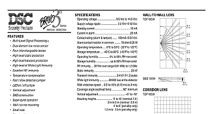
Installation Instructions d de instalaci Digital Bravo3 PIR detector is designed to provide maximum detection and false alarm prevention in both residential and commercial applications It uti a microcontroller to weigh the strength of the digitalized PIR signal at different lev MLSP algorithm in order to provide effective detection of human motion Digital Bravo3 technology adapts to changing environmental conditions by adjusting critical detection parameters in order to improved consistency of detection over all temperature ranges The detector also provides excellent immunity to such false producing influences as RF static and electrical transient This technology plus exceptional design care and careful factory ensure years of trouble free performance interchangeable lenses wall or corner mounting and vertical adjustment provide application versatility Your clients will the small size and elegant simplicity of the case design Digital Bravo3 has a 5 year warranty your assurance of a trouble free installation by the following patents Canada 2099971 US 5444432 The Detector a detector location that will provide the coverage required Consider the following to avoid false alarms Do not aim the detector at reflective surfaces such as mirrors or windows as this may distort the coverage pattern or reflect sun directly onto the detector Avoid locations that are subject to direct high air flow such as near an air duct outlet Do not locate the detector near sources of moisture such as steam or oil Do not locate the detector in the path of direct or reflected mirror sunlight For premises with pets use the pet alley lens Do not limit the coverage by large obstructions in the detection area such as plants or cabinets open the case use a small flat blade screwdriver and gently push in the tab at the bottom of the case and pull the cover straight at the bottom Loosen the PCB screw and push the board up as far as it will go Using a small screwdriver remove the appro knockouts for the mounting screws Remove the left and or right wiring entrance knockouts located at the top of the back Mount the backplate to the wall using the screws supplied Adjustment Range and dead zones may vary due to settings the Mounting Height Chart see back set the vertical adjustment for the desired coverage The height will be indicated by gauge located at the bottom right hand corner of the circuit board Ensure that the PCB retaining screw is tightened just enough prevent board movement the circuit board down will increase the far range and move the near beams farther out from the mounting wall the circuit board up will reduce the far range and bring the near beams closer to the mounting wall Moving the board too much will cause the far beams to above the target As a result the range may appear shorter are two jumpers on the detector circuit board JUMPER J1 will enable disable the alarm LED If J1 is OFF the LED will not on alarm If J1 is ON the LED will operate on alarm power up if J1 is ON the LED will blink on and off at one second intervals for 50 seconds to indicate warm up period J2 selects between normal and hostile operation For a typical environment the unit should be set to J2 ON If environment presents potential disturbances which cannot be avoided set J2 to J2 OFF When using the corridor lens set J2 to ON Lenses detector is supplied with the wall to wall lens BV L1 To change the lens release the top tab and pull the lens holder out action releases the lens Insert the new lens with the GROOVES FACING INWARD The bottom of the lens is indicated by two tri indentations Ensure that the lens is centered and then reattach the lens holder The lens holder will snap into place sealing lens into position The corridor lens should not be used for corridors less then 6 1.8m wide Ensure the beams are aimed directly down the of corridor Testing NOTE Upon installation the unit should be thoroughly tested to verify proper operation The end user should be on how to perform a walk test weekly the detector has been set up create motion in the entire area where coverage is desired by walking perpendicular to the lens Should the coverage be incomplete readjust or relocate the detector Once coverage is as required the alarm LED may be by setting J1 to OFF d Digital Bravo3 est un d de mouvement infrarouge con pour fournir maximum de d de mouvement et pour am la pr des fausses dans les installations r et commerciales utilise un microcontr pour mesurer la force du signal infrarouge divers niveaux MLSP afin d une d efficace des mouvements humains technologie du Digital Bravo3 s aux changements des conditions de l en ajustant les param essentiels d afin de fournir une meilleure d quelle que soit la temp Le d poss une excellente aux fausses alarmes provoqu par les radiofr l statique et les courants transitoires Cette technologie que la conception extr soign et les tests en usine minutieux assurent des ann performantes sans probl lentilles interchangeables une installation au mur ou dans un coin et un r vertical offrent une polyvalence d sera appr par votre client en plus des dimensions compactes de l et de la simplicit du bo mod Digital Bravo3 poss une garantie de cinq ans assurance d installation sans probl par les brevets suivants Canada 2099971 US 5444432 du d un emplacement offrant la couverture n en tenant compte des probl potentiels suivants Ne pas orienter le d sur des surfaces r telles que des miroirs ou des vitres Cela pourrait alt la couver ou provoquer la r des rayons du soleil directement sur le d les emplacements soumis un d d tels que les environs de la sortie d conduit d Ne pas installer le d proximit de sources d comme de vapeur ou d S y a des animaux sur les lieux utiliser la lentille pour animaux Ne pas orienter le d de fa ce qu re des rayons lumineux solaires directs ou r Ne pas limiter la couverture en pla des obstructions comme des plantes ou des armoires dans la zone de d ouvrir le bo utiliser un petit tournevis t plate et pousser avec soin la languette de la partie inf du bo puis le couvercle tout droit par le dessous Desserrer la vis de la carte de circuit imprim et pousser la carte aussi haut que possible l d petit tournevis enlever les alv d appropri pour les vis de montage Enlever l de gauche et de droite pour entr de c sur la partie sup de la plaque arri Installer la plaque arri l des vis fournies vertical La port et la zone morte peuvent varier selon les r consultant le tableau de la port en fonction de la hauteur d effectuer le r vertical de fa obtenir la couverture S que la vis de fixation de la carte de circuit imprim est juste assez serr pour emp le mouvement de la carte d le PCB vers le bas la port du d augmentera et les faisceaux s du mur sur lequel le d est En d le PCB vers le haut la port du d diminuera et les faisceaux s au mur sur lequel le d situ Si l d trop en bas les faisceaux au dessus du cible En cons la port semblera plus courte y a deux cavaliers sur la plaquette de circuit du d CAVALIER J1 Ce cavalier permet de mettre en circuit hors circuit la DEL Si J1 n PAS enfich la DEL ne s