DSC BV-300P - Installation Manual - English - Bravo3 Digital Pet-Immune Passive Infrared Motion Detector

File Preview
Click below to download for free
Click below to download for free
File Data
| Name | dsc-bv-300p-installation-manual-english-bravo3-digital-pet-immune-passive-infrared-motion-detector-8153497206.pdf |
|---|---|
| Type | |
| Size | 665.66 KB |
| Downloads |
Text Preview
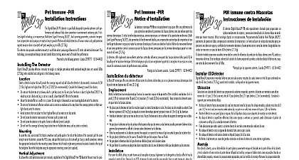
Coverage View PIR INSTRUCTIONS 9m Bravo3P is a general purpose PIR detector designed to reliable motion detection and enhanced false alarm in environments containing pets It utilizes Multi Level Processing temperature compensation and a unique pet lens to provide effective detection of human motion and protection against nuisance alarms associated with single multiple pets whose total combined weight does not exceed 27.3kg The detector also provides immunity against false caused by RF static and electrical transients Exceptional care and factory testing ensure years of trouble free Protected by one or more of the following patents 2099971 US 5444432 voltage 9.5VDC 14.5VDC voltage ripple 3.0V PP 12VDC current 16mA in alarm 20mA rating 100mA 24VDC contact resistor in common 10 1 4W temp 15 to 30 59 to 86 temp 40 to 60 104 to 140 4 7.2 2ft s humidity 5 95 RH non cond humidity up to 99 RH non cond immunity 10 V m plus 80 AM from 80MHz to 1GHz immunity 8kV contact 15 kV air immunity 2.4kV 1.2 joules detection speed 0.5 4 s 0.15 1.22m s angle 60 minimum 75 maximum mounting height 7.5 2.3m UL tests only the 85 RH non cond RF immunity was not tested by UL Pet immunity has not been verified by UL BV 300P Form alarm contact View 12m 12m optimum detection the BV 300P should be located so that the expected of intrusion is between 10ft 40ft 3m 12m in front of the detector The Detector choosing a mounting location for the detector consider following to help prevent false alarms Mount the detector flat on a wall or in a corner Do not angle downwards The unit must be installed so that the expected path of is perpendicular to the detection pattern The PCB must be positioned so that the vertical adjustment on the board is set to zero Ensure PCB retaining screw been tightened Mount the detector at a minimum height of 7.5ft 2.3m Do not aim the detector at a stairway to which a pet has access Do not place furniture or objects higher than 3ft 0.9m which pet can jump onto at a distance of less than 6ft 1.8m away the detector Do not aim the detector at reflective surfaces such as a mirrors windows flow Do not locate the detector near sources of moisture or high Do not use this detector in a room of extreme high low open the case use a small flatblade screwdriver gently push the tab at the bottom of the case and pull the cover straight at the bottom Loosen the PCB screw and push the board as far as it will go Using a small screwdriver remove the knockouts for the mounting screws Remove the and or right wiring entrance knockouts located at the top the backplate Mount the backplate to the wall using the supplied Adjustment achieve the performance and pet immunity capabilities of the the PCB must be positioned so the vertical adjustment on the board is set to zero Ensure the PCB retaining screw tightened just enough to prevent board movement is one jumper on the detector circuit board JUMPER J1 will the alarm LED If J1 is OFF the LED will not operate alarm If J1 is ON the LED will operate on alarm This unit is UL Listed and should be connected to a Listed unit or power supply providing at least 4 hours of standby 12VDC Contacts 24VDC shown with power applied and no alarm Testing NOTE Once installed the unit should be thoroughly to verify proper operation After installation the unit be tested annually by the installer The end user should be on how to perform a weekly walk test the animal s within the coverage area of the detector and then out of the zone Encourage the pet s to move around normally ensure they move across the detection pattern of the detector that no alarm is initiated test for catch performance of humans create motion in the area where coverage is desired by walking perpendicular to lens pattern Should the coverage be incomplete readjust or the detector Once coverage is as required the alarm LED be disabled by setting J1 to OFF GND C knockouts screw for adjustment adjustment Warranty Security Controls Ltd warrants that for a period of 12 months from the of purchase the product shall be free of defects in materials and workmanship normal use and that in fulfilment of any breach of such warranty Digital Controls Ltd shall at its option repair or replace the defective upon return of the equipment to its repair depot This warranty only to defects in parts and workmanship and not to damage incurred in or handling or damage due to causes beyond the control of Digital Controls Ltd such as lightning excessive voltage mechanical shock damage or damage arising out of abuse alteration or improper application the equipment foregoing warranty shall apply only to the original purchaser and is and shall in lieu of any and all other warranties whether expressed or implied and of all other or liabilities on the part of Digital Security Controls Ltd Digital Controls Ltd neither assumes responsibility for nor authorizes any other purporting to act on its behalf to modify or to change this warranty nor to for it any other warranty or liability concerning this product no event shall Digital Security Controls Ltd be liable for any direct indirect or damages loss of anticipated profits loss of time or any other losses by the buyer in connection with the purchase installation or operation or of this product detectors can only detect motion within the designated areas as shown their respective installation instructions They cannot discriminate be intruders and intended occupants Motion detectors do not provide area protection They have multiple beams of detection and motion only be detected in unobstructed areas covered by these beams They cannot motion which occurs behind walls ceilings floor closed doors glass glass doors or windows Any type of tampering whether inten or unintentional such as masking painting or spraying of any material the lenses mirrors windows or any other part of the detection system will its proper operation infrared motion detectors operate by sensing changes in temperature their effectiveness can be reduced when the ambient temperature rises or above body temperature or if there are intentional or unintentional sources heat in or near the detection area Some of these heat sources could be heaters stoves barbeques fireplaces sunlight steam vents lighting and so on Digital Security Controls Ltd recommends that the entire system completely tested on a regular basis However despite frequent testing due to but not limited to criminal tampering or electrical disruption is possible for this product to fail to perform as expected Information Changes or modifications not expressly approved Digital Security Controls Ltd could void the user authority to operate equipment Digital Security Controls Ltd Canada www dsc com in Canada 29005279 R002 View PIR INSTRUCTIONS 9m Bravo3P is a general purpose PIR detector designed to reliable motion detection and enhanced false alarm in environments containing pets It utilizes Multi Level Processing temperature compensation and a unique pet lens to provide effective detection of human motion and protec


