DSC BV-600 - Installation Manual - English - Bravo6 Twin, Dual-Element Pet-Immune Passive Infrared Motion Detector

File Preview
Click below to download for free
Click below to download for free
File Data
| Name | dsc-bv-600-installation-manual-english-bravo6-twin-dual-element-pet-immune-passive-infrared-motion-detector-2394867510.pdf |
|---|---|
| Type | |
| Size | 677.30 KB |
| Downloads |
Text Preview
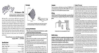
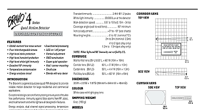
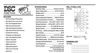
Dual PIR Detector View Operating voltage 9.5 VDC to 14.5 VDC Supply voltage ripple 3.0 VP P 12 VDC Stand by current 16.5 mA Current in alarm LED on 17.5 mA Contact rating alarm tamper 100 mA 24 VDC Alarm contact resistor in common 28 ohm 0.25 W Operating temperature 32 to120 0 to 49 Storage temperature 40 to140 40 to 60 Operating humidity 5 to 93 RH non condensing Storage humidity up to 99 RH non condensing Radiated RF immunity V m with 80 AM over range 27MHz to 1.0GHz Conducted RF immunity with 80 AM over range 150kHz to 80MHz Static immunity 15 kV Transient immunity 2.4 kV 1.2 joules Walk detection speed 0.5 to 10 0.15 m s to 3 m s Coverage angle wall wall lens 100 maximum Vertical adjustment 2 to 5 Mounting heights to 10.5 2.1m to 3.2m nominal 7.5 2.3m H 2.76 W 1.75 D 124.5 mm 70 mm 44.5 mm with white lens BV 600 PBV 600 Form A alarm contact BV 601 PBV 601 Form A alarm contact tamper switch BV 602 PBV 602 Form C alarm contact tamper switch Patterns for Bravo 6 Series Lens View INSTRUCTIONS INSTRUCTIONS Bravo 6 is a specialized twin dual PIR motion sensor emphasizes immunity from false alarms caused by The Bravo 6 is equipped with a specially designed which enables the detector to discriminate between and small to mid sized pets design care and factory testing ensure years trouble free performance Immunity against false from RF static electrical transients and white are all DSC designed in features Signal Processing temperature and large multi beam lens design means human target will not slip by unnoticed even on a hot day or corner mounting and vertical adjustment provide versatility and your client will appreciate the size and elegant simplicity of the case design Immune to pets under 2.5 ft 0.75 m up to 85 lbs 38 kg Microprocessor based Advanced Multi Level Signal MLS Processing Twin dual element low noise sensors High level static protection High level transient protection UV stable lens High level of white light immunity Excellent RF immunity DSC Temperature compensation circuitry Harsh Normal environment jumper LED on off jumper Vertical adjustment SMD construction Super quiet operation Wall Corner mounting Blends with any decor Compact size Protected by one or more of the following patents CA2196014 US 5923250 Protected by one or more of the following patents 2099971 US 5444432 the Detector a detector location that will provide the coverage keeping in mind the following potential problems Surfaces not aim the detector at reflective surfaces such as or windows as this may distort the coverage pattern reflect sunlight directly onto the detector Flow locations that are subject to direct high air flow such near an air duct outlet not locate the detector near sources of steam or oil Sun not aim the detector such that it will receive direct or mirror sunlight not limit the coverage by large objects within the area such as plants or filing cabinets Rejection not aim the detector at a stairway which a pet has to not place furniture or objects higher than 3 ft 0.9 m a pet can climb onto e g a cat on a couch closer 7 ft 2.1 m to the detector This unit is UL Listed and should be connected a listed control unit or power supply providing at 4 hours of standby power Testing Once the detector has been set up walk test the entire where coverage is desired Should the coverage be readjust or relocate the detector to obtain full Once coverage is as required the alarm LED be disabled by setting J1 to OFF NOTE Upon installation the unit should thoroughly tested to verify proper operation The user should be instructed on how to perform walk and should walk test the detector weekly open the case use a small flat blade screwdriver and push in the tab at the bottom of the case and pull the straight out at the bottom Loosen the printed circuit screw and push the board up as far as it will go Using small screwdriver remove the appropriate knockouts for mounting screws Remove the desired wiring entrance located at the top or bottom of the backplate the backplate screws diagonally opposite to each other to prevent warpage Height Guide 2.1 m 2.3 m 2.6 m 2.7 m 3.2 m 0.25 0.50 1.00 1.50 Adjustment Range and dead zones may vary due to settings the Mounting Height chart set the vertical adjustment get the desired coverage Ensure that the PCB retaining is tightened just enough to prevent board movement the circuit board DOWN will increase the far range move the near beams farther out from the mounting Moving the circuit board UP will reduce the far range bring the near beams closer to the mounting wall the circuit board DOWN too much will cause the far to above the target as a result the range may shorter J1 will enable disable the alarm LED If J1 is OFF LED will not operate on alarm If J1 is ON the LED will on alarm Jumper J2 selects between harsh and environments For a typical environment or one a small pet lower than 1.2 ft 0.36 m set the unit normal J2 ON For a large pet and multiple pets the J2 should be removed Warranty Security Controls Ltd warrants that for a period of twelve months from the of purchase the product shall be free of defects in materials and workmanship normal use and that in fulfilment of any breach of such warranty Digital Controls Ltd shall at its option repair or replace the defective equipment return of the equipment to its repair depot This warranty applies only to defects parts and workmanship and not to damage incurred in shipping or handling or due to causes beyond the control of Digital Security Controls Ltd such as excessive voltage mechanical shock water damage or damage arising of abuse alteration or improper application of the equipment foregoing warranty shall apply only to the original buyer and is and shall be in of any and all other warranties whether expressed or implied and of all other or liabilities on the part of Digital Security Controls Ltd Digital Security Ltd neither assumes nor authorizes any other person purporting to act on behalf to modify or to change this warranty nor to assume for it any other or liability concerning this product no event shall Digital Security Controls Ltd be liable for any direct indirect or damages loss of anticipated profits loss of time or any other losses by the buyer in connection with the purchase installation or operation or of this product detectors can only detect motion within the designated areas as shown in respective installation instructions They cannot discriminate between intrud and intended occupants Motion detectors do not provide volumetric area pro They have multiple beams of detection and motion can only be detected in areas covered by these beams They cannot detect motion which oc behind walls ceilings floor closed doors glass partitions glass doors or Any type of tampering whether intentional or unintentional such as mask painting or spraying of any material on the lenses mirrors windows or any part of the detection system will impair its proper operation infrared motion detectors operate by sensing changes in temperature How their effectiveness can be reduced when the ambient temperature rises near or body temperature or if there are intentional or unintentional sources of heat in near the detection area Some of these heat sources could be heaters radiators barbeques fireplaces sunlight steam vents lighting and so on Digital Security Controls Ltd recommends that the entire system be