DSC CFP 102 CFP 105 IM EN NA BATTERY CALCULATIONS

File Preview
Click below to download for free
Click below to download for free
File Data
| Name | dsc-cfp-102-cfp-105-im-en-na-battery-calculations-7861250493.pdf |
|---|---|
| Type | |
| Size | 609.25 KB |
| Downloads |
Text Preview
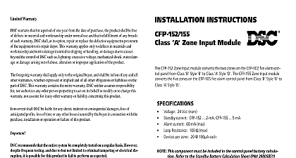
CFP 102 CFP 105 CFP 105 Alarm Control Panel for Standby Battery Requirement per mA device Standby mA Alarm mA 415 1 2 3 4 5 1 2 Rev Box 2 5 90 130 415 15 15 33 20 Note 4 20 0 1 1 1 1 1 1 1 90 130 and current mA and mA by 1000 time required 24 or 60 Hr Amp Hr multiply 7 8 Amps Hr time required 5 min 08 Hr Amp Hr multiply 7 10 Amps Hr Amp Hr standby Amp Hr 9 alarm Amp Hr 11 Multiply the total Amp Hr by the safety margin 1 Select a battery with an Amp Hr rating that is equal to or larger than the calculated minimum Amp Total battery Amp Hr required to support the system 1.20 battery required Note The maximum battery allowed is 12 Ah 2 For the relay module add 8 mA as for each relay programmed for and add 8 mA for each relay programmed for 3 The Class A modules do not add any or current above that calculated for each zone 4 When the CFP 161 is used as a Polarity reversal transmitter add the current draw of the remote input in the mode 5 For panels used in a Station application 60 Hr standby the dialer may be but no current may be drawn from the AUX output Battery Chart components that draw current from the panel while it is in the mode AC must be considered for the standby battery calculation All components that draw while in the mode must be considered for the alarm battery calculation 1 2 control panel will always draw the currents as shown in the chart the alarm current is calculated assuming only one initiating zone is alarm If it is required that more than one zone be considered add 60 mA zone in the Alarm column Consult the smoke detector manufacture sheet to determine the standby current of these devices Write number in the per device column then multiply that number by number of devices on the zone Repeat for each zone 3 Consult the Notification Appliance installation sheet to determine the current for each device connected to the NAC For each NAC calculate the total in alarm and put that number mA in the column Note each can supply 1.5 Amps max and the output voltage is 24 volts FWR 4 Add up all the current drawn from the AUX output in the standby and alarm 5 and put those totals in the and columns each module added to the system multiply the number of modules times module and currents and write those totals in the and columns 6 Add up all the currents in the column and the column 7 Convert the and currents from mA to Amps divide mA by 8 Write in the time required 24 or 60 Hr 9 Multiply the Amps times the time to get the required 10 Write in the time required in hours 5 min 08 Hr 11 Multiply the Amps times the time to get the Amp Hr 12 Add the Amp Hr to the Amp Hr for the total Amp Hr 13 Multiply the total Amp Hr times 1.20 for the minimum Amp Hr battery to support the system for the selected time and the time details on the control panel and modules see their respective installation docu Please refer to the System Instruction manual for information on limita regarding product use and function and information on the limitations as to of the manufacturer 2001 Digital Security Controls Ltd Toronto Canada www dsc com Help Desk Canada US 1 800 387 3630 Printed in Canada cid 127 29005851 R001