DSC CFP200-205 im na eng

File Preview
Click below to download for free
Click below to download for free
File Data
| Name | dsc-cfp200-205-im-na-eng-8659472301.pdf |
|---|---|
| Type | |
| Size | 671.18 KB |
| Downloads |
Text Preview
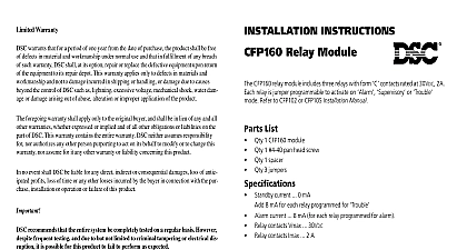
Limited Warranty warrants that for a period of one year from the date of purchase the product shall be free defects in material and workmanship under normal use and that in fulfillment of any breach such warranty DSC shall at its option repair or replace the defective equipment upon return the equipment to its repair depot This warranty applies only to defects in materials and and not to damage incurred in shipping or handling or damage due to causes the control of DSC such as lightning excessive voltage mechanical shock water dam or damage arising out of abuse alteration or improper application of the product foregoing warranty shall apply only to the original buyer and shall be in lieu of any and all warranties whether expressed or implied and of all other obligations or liabilities on the of DSC This warranty contains the entire warranty DSC neither assumes responsibility nor authorizes any other person purporting to act on its behalf to modify or to change this nor assume for it any other warranty or liability concerning this product no event shall DSC be liable for any direct indirect or consequential damages loss of antic profits loss of time or any other losses incurred by the buyer in connection with the pur installation or operation or failure of this product recommends that the entire system be completely tested on a regular basis However frequent testing and due to but not limited to criminal tampering or electrical dis it is possible for this product to fail to perform as expected INSTRUCTIONS Remote Trouble Unit Remote Trouble Unit CFP200 Remote Trouble Unit provides remote trouble annunciation for the CFP102 fire alarm control panels The CFP205 Remote Trouble and Alarm Unit provides trouble annunciation for the CFP102 105 series fire alarm control panels A maxi of four CFP200 and four CFP205 units can be connected to each control panel current 15 mA 24 VDC to 8 addressable units of each type AUX COM from control panel AC ON indicator Common Trouble indicator Silence pushbutton Test function DAT CLK from panel This component must be included in the control panel battery calcula Refer to the Standby Battery Calculation Sheet PN 29005851 with the control panel 1 2 3 4 5 Digital Security Controls Ltd Canada cid 127 1 800 387 3630 cid 127 www dsc com in Canada 29005820 R003 current 25 mA max gang mounting 3 4 x 4 1 2 70 mm x 115 mm current 40 mA max gang mounting 1 2 x 4 1 2 115 mm x 115 mm Supervisiory LED Zone CFP200 module mounts in a single gang box The CFP205 mounts in a double outlet box Refer to Figures 1 2 and 1 2 Configure jumpers item 1 for desired address Affix zone identification labels if required the label aligned with the LED indica CFP205 Only Route Secur Bus wiring through the out box Connect the 4 wires to the termi item 2 on the PC board Position the module in the outlet box and with the screws item 3 provided screws for the CFP200 4 screws for the Secure the front panel item 4 to module the screws provided item 5 AC and Trouble LEDs on the remote units the control panel AC and Trouble LEDs the Trouble Silence switch at the or at any remote unit will silence the buzzer at the panel and all remote indicators on the remote units follow the indicators of the control panel The red will operate if the panel zone is pro for and the yellow LED will if the panel zone is programmed for Lamp Test is initiated by pressing and the Trouble Silence pushbutton for 1 2 The LEDs will flash until the button is 1 Address Programming 2 Secur Bus Wire Run Chart AWG AWG