DSC CT-8 - Installation Manual - English - Communique Cable Tester

File Preview
Click below to download for free
Click below to download for free
File Data
| Name | dsc-ct-8-installation-manual-english-communique-cable-tester-9701238456.pdf |
|---|---|
| Type | |
| Size | 592.20 KB |
| Downloads |
Text Preview
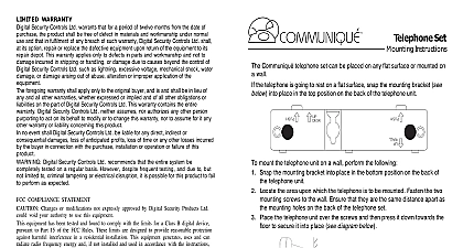
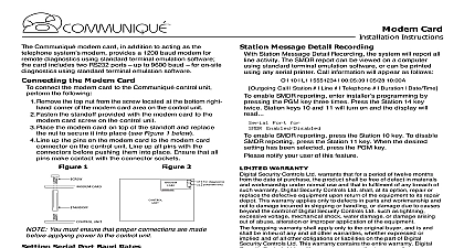
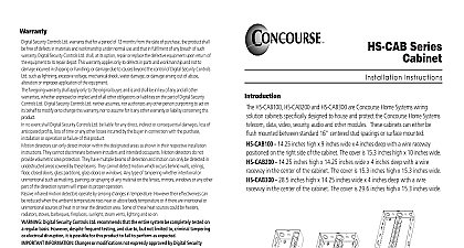
CT 8 Cable Tester Instructions CT 8 cable tester is designed to be used by qualified personnel only The cable tester should only be used to test inactive cables CT 8 cable tester is a device used to test modular cable for defects shorts opens The CT 8 will test any cable from 1 pair up to 4 pair which is terminated with plugs on both ends The sets of four lights on the transmitter and receiver will normal or irregular wiring conditions according to how they light up cable tester has two parts One CT 8T Transmitter Unit a battery operated electronic sequence generator with green LEDs and two modular jacks one 8 pin and one 6 pin One CT 8R Receiver Unit four green LEDs four red LEDs and two modular jacks one and one 6 pin of Conductors using four six or eight conductor cables the conductors are identified by number 1 6 or 1 8 from left to right when looking at the plug with the tab facing towards you the Cable Tester the cable you wish to test Plug one modular connector into the appropriate jack or 8 pin on the transmitter unit plug the other modular connector into the appropriate on the receiver unit The units will complete a circuit through the two wires in each of the cable one at a time continuously cycling through up to four pairs the sets of four LEDs on the transmitter and receiver units When testing 1 pair cable 1 will represent the two conductors For 2 to 4 pair cables each pair of conductors will be by one of the four sets of lights according to the following table Cable Type Conductor Conductor Conductor pair 2 and 3 1 and 4 pair 3 and 4 2 and 5 1 and 6 pair 4 and 5 3 and 6 2 and 7 1 and 8 green lights on the cable tester transmitter and either the green or the red lights on the unit will flash if the cable is in good working order If the green lights on the receiver flash the cable is swapped and in good working order If the red lights on the receiver flash the cable is straight through and in good working order The lights on the two units flash simultaneously following patterns indicated in the following table of pairs pair pair pair pair deviation from this flashing pattern means that one or more of the conductors are flashing pattern pause 1 pause 1 pause 2 pause 1 2 pause 2 3 pause 1 2 3 pause 2 3 4 pause 1 2 3 4 pause WARRANTY Security Controls Ltd warrants that for a period of twelve months from the date of purchase product shall be free of defect in materials and workmanship under normal use and that in of any breach of such warranty Digital Security Controls Ltd shall at its option repair or the defective equipment upon return of the equipment to its repair depot This warranty only to defects in parts and workmanship and not to damage incurred in shipping or handling damage due to causes beyond the control of Digital Security Controls Ltd such as lightning voltage mechanical shock water damage or damage arising out of abuse alteration or application of the equipment foregoing warranty shall apply only to the original buyer and is and shall be in lieu of any and other warranties whether expressed or implied and of all other obligations or liabilities on the part Digital Security Controls Ltd This warranty contains the entire warranty Digital Security Controls neither assumes nor authorizes any other person purporting to act on its behalf to modify or change this warranty nor to assume for it any other warranty or liability concerning this product no event shall Digital Security Controls Ltd be liable for any direct indirect or consequential loss of anticipated profits loss of time or any other losses incurred by the buyer in with the purchase installation or operation or failure of this product Digital Security Controls Ltd recommends that the entire system be completely tested a regular basis However despite frequent testing and due to but not limited to criminal or electrical disruption it is possible for this product to fail to perform as expected COMPLIANCE STATEMENT Changes or modifications not expressly approved by Digital Security Products Ltd could void authority to use this equipment equipment has been tested and found to comply with the limits for a Class B digital device pursuant Part 15 of the FCC Rules These limits are designed to provide reasonable protection against harmful in a residential installation This equipment generates uses and can radiate radio frequency and if not installed and used in accordance with the instructions may cause harmful interference to communications However there is no guarantee that interference will not occur in a particular If this equipment does cause harmful interference to radio or television reception which can be by turning the equipment off and on the user is encouraged to try to correct the interference by or more of the following measures Re orient the receiving antenna Increase the separation between the equipment and receiver Connect the equipment into an outlet on a circuit different from that to which the receiver is connected Consult the dealer or an experienced radio television technician for help user may find the following booklet prepared by the FCC useful to Identify and Resolve Radio Interference Problems This booklet is available from the U S Government Printing Office D C 20402 Stock 004 000 00345 4 Security Products Ltd 160 Washburn St Lockport NY 14094 Digital Security Controls Ltd Flint Road Downsview Ontario Canada M3J 2J6 665 8460 1 800 387 3630 in Canada 29002792 R0