DSC DC3000i-Installation Manual--English

File Preview
Click below to download for free
Click below to download for free
File Data
| Name | dsc-dc3000i-installation-manual-english-3706928415.pdf |
|---|---|
| Type | |
| Size | 1.23 MB |
| Downloads |
Text Preview
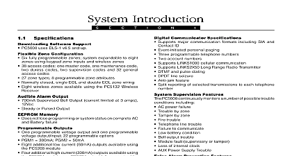
DC6000iiiii Communicator 2001 SG Security Communications Division of Sur Gard Security Systems Ltd R001 in Canada Manual 1.0 Warranty Security Communications warrants that for a period of twelve months from date of purchase the product shall be free from defects in materials and under normal use and that in fulfillment of any breech of such SG Security Communications shall at its option repair or replace the equipment upon return of the equipment to its repair depot This applies only to defects in parts and workmanship and not to damage in shipping or handling or damage due to causes beyond the control SG Security Communications such as lightning excessive voltage mechanical water damage or damage arising out of abuse alteration or improper of the equipment foregoing warranty shall apply only to the original buyer and is and shall be lieu of any and all other warranties whether expressed or implied and of all obligations or liabilities on the part of SG Security Communications SG Communications neither assumes responsibility for nor authorizes any person purporting to act on its behalf to modify or to change this warranty to assume for it any other warranty or liability concerning this product no event shall SG Security Communications be liable for any direct or indirect consequential damages loss of anticipated profits loss of time or any other incurred by the buyer in connection with the purchase installation or or failure of this product SG Security Communications recommends that the entire system SG Security Communications recommends that the entire system SG Security Communications recommends that the entire system SG Security Communications recommends that the entire system SG Security Communications recommends that the entire system completely tested on a regular basis However despite frequent testing completely tested on a regular basis However despite frequent testing completely tested on a regular basis However despite frequent testing completely tested on a regular basis However despite frequent testing completely tested on a regular basis However despite frequent testing due to but not limited to criminal tampering or electrical disruption it due to but not limited to criminal tampering or electrical disruption it due to but not limited to criminal tampering or electrical disruption it due to but not limited to criminal tampering or electrical disruption it due to but not limited to criminal tampering or electrical disruption it possible for this product to fail to perform as expected possible for this product to fail to perform as expected possible for this product to fail to perform as expected possible for this product to fail to perform as expected possible for this product to fail to perform as expected Indicators the bottom left of the module there are 2 LEDs to indicate the status of the The NT OK light will be on to indicate the S BUS is working correctly If light is off there is no S BUS or there is a wiring problem between the NT1 the DC6000i or there is no power to the module CS OK LED indicates the status of the call In normal operation this LED be off The LED will flash when dialing a central station and will remain when transmitting data to the central station the BUS OUT there is one more red LED This LED will only activate when module has physically disconnected to BUS OUT because of a trouble on the S BUS or due to the programming of the module when trans to the central station the DC6000i is done via the PC5015 ISDN telephone number sec installer address 301 first telephone number The transmitted account is also programmed in the PC5015 ISDN installer programming at sec 310 an alarm call from the panel the DC6000i operation reads the receiver number string format programmed in the panel telephone number format new receiver telephone number format programmed in the panel is Indicates to the module to use the panel account number Local subscriber number for the DC6000i connected to MSN must be unique The digital central station receiver telephone number The analogue central station receiver telephone number The DC6000i guard mode to be applied 0 1 or 2 Either C or D may be programmed However it is possible to program first and second receiver telephone numbers differently to two different of receivers When sending to the analogue receiver the DC6000i utilizes SIA protocol Modes of the DC6000i guard mechanism can be specified by the option the receiver telephone number string The options are 0 No action Never disconnect the line This is not recommended 1 Disconnect 1 B channel if no channel is available Recommended 2 Disconnect all B channels and physically disconnect the secondary S0 Guard Mechanism DC6000i comes with an intelligent S0 bus monitor that enables it to disconnect devices and thus ensures 100 availability of the ISDN network for alarm In contrast to analog systems where the panel is equipped with a relay to the analogue line to be available at any time with standard ISDN systems there no such priority mechanism for the alarm panel Since up to eight terminal adaptors share the same physical ISDN S0 bus and two simultaneous calls B1 and B2 are it is very likely that there will not be a channel available to alarm panel when an alarm has to be transmitted to the central station fig 1.0 below 1.0 Typical ISDN security system set up Fig 1.0 the alarm panel cannot connect to the central station because there two other devices on the same ISDN S0 bus that already occupy the two B Another error in this example is the lack of ISDN S0 bus tamper Imagine someone shortening the ISDN S0 bus near the fax machine will disable communications for the devices including the alarm panel and its party ISDN terminal adapter The guard mechanism of the DC6000i ISDN offers both a tamper protection mechanism and an intelligent mechanism disconnect other device connections 1.1 Correct ISDN security system set up 1.1 shows the correct way of setting up your ISDN security system using DC6000i ISDN adapter In case of ISDN S0 bus tamper the DC6000i will malfunctioning of the S0 bus and will physically disconnect other devices the tamper source is no longer connected to the DC6000i the alarm panel able to continue normal operation five minutes the DC6000i adapter reconnects the secondary S0 bus to see the tamper source is still present If the tamper source has disappeared the bus stays connected If not the DC6000i will immediately disconnect secondary S0 bus again and it will follow the same procedure in five minutes to the PC5015 ISDN the DC6000i 3 pin header to the PC5015 ISDN PC Link header with supplied cable It is not recommended to make any modifications to the This connection will provide the communication information to the DC6000i Next connect the positive 12v and Ground from the PC5015 ISDN aux output This will provide power to the module DC6000i Specifications Board size L x W 5.50 x 3.25 13.97cm x 8.255cm Voltage 12VDC from panel Current 150mA S0 Network Connection Physical RJ45 socket Basic Rate Interface Protocols Euro ISDN ETS300 102 HDLC Analogue Protocol Bell 103 300baud SIA level 1 2 Mode of Operation Point to point or Point to multipoint Secure S0 Physical shielded RJ45 socket connection to panel Physical 3 pin header to the PC5015 ISDN the DC6000i 3 pin header to the PC5015 ISDN PC Link header with supplied cable It is not recommended to make any modifications to the This connection will provide the communication information to the DC6000i Next connect the positive 12v and Ground from the PC5015 ISDN aux output This will provide power to the module DC6000i Specifications Board size L x W 5.50 x 3.25 13.97cm x 8.255cm Voltage 12VDC from panel Current 150mA S0 Network Connection Physical RJ45 socket Basic Rate Interface Protocols Euro ISDN ETS300 102 HDLC Analogue Protocol Bell 103 300baud SIA level 1 2 Mode of Operation Point to point or Point to multipoint Secure S0 Physical shielded RJ45 socket connection to panel Physical 3 pin header