DSC F2-211-Installation Sheet-UK-English

File Preview
Click below to download for free
Click below to download for free
File Data
| Name | dsc-f2-211-installation-sheet-uk-english-7850412936.pdf |
|---|---|
| Type | |
| Size | 835.15 KB |
| Downloads |
Text Preview
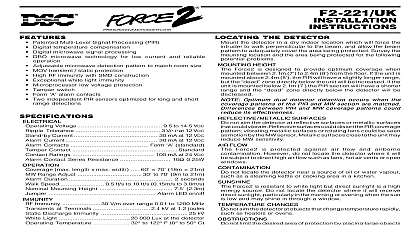
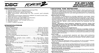
THE DETECTOR MOTION DETECTOR Patented Multi Level Signal Processing PIR Digital microwave signal processing DRO microwave technology for low current and reliable MOV transient static protection High RF immunity with SMD construction Exceptional white light immunity Microprocessor low voltage protection Tamper switch Form alarm contacts Voltage 9.5 to 14.5 VDC Tolerance 3 VP P at 12 VDC Current 30 mA at 12 VDC Current 30 mA at 12 VDC Contacts Form standard Contact Standard Ratings 100 mA at 24 VDC Contact Series Resistance 10 0.25W max length x max width 30 40 9m 12m Duration 2 seconds Speed 0.5 ft s to 10 ft s 0.15m s to 3.0m s Mounting Height 7.5 2.3m Alarm LED on off Immunity 30 V m over range 0.01 to 1200 MHz at Terminals 2.4 kV at 1.2 joules Discharge Immunity 25 kV Light 20 000 Lux at the detector Temperature 32 to 122 F 0 to 50 C 5 to 95 RH non condensing Force2 211 is a short range dual detector employing both MW and passive infrared PIR motion sensors The are combined through a microprocessor to provide motion detection designed to eliminate single detector alarms technical features such as the PIR s Multi Level Signal MLSP a highly reliable DRO microwave sensor and MW signal analysis combine for a new level of detection stability and false alarm immunity PIR and MW systems are each designed as independent high motion detectors When combined the result is a detector unmatched performance detector indicates an alarm when both sensors detect motion 10 seconds of each other The first sensor either the PIR or which detects motion will start the 10 second confirmation during which the other sensor must also detect motion If first sensor detection is not confirmed within 10 seconds the disregards the alarm MW BEAM PATTERNS the detector in a dry indoor location which will force the to walk perpendicular to the beam and allow the beam to adequately cover the area being protected Survey the location and the area being protected for the following problems HEIGHT Force2 is designed to provide optimum coverage when between 2.1m 7 to 2.4m 8 from the floor If the unit is above 2.4m 8 the PIR will have a slightly longer range the zone directly below the unit will be increased If the is mounted below 2.1m 7 the PIR section will have a shorter and the zone directly below the detector will be METALLIC SURFACES not aim the detector at reflective surfaces or metallic surfaces could vibrate Reflective surfaces could distort the PIR coverage vibrating metallic surfaces or rotating fans could be seen motion by the MW sensor Metallic surfaces close to the unit may MW sensitivity FLOW Force2 is protected against air flow and airborne However do not locate the detector where it will subject to direct high air flow such as fans hot air vents or open not locate the detector near a source of oil or water vapour as a steaming kettle or cooking area in a kitchen Force2 is resistant to white light but direct sunlight is a high source Do not locate the detector where it will receive sunlight particularly in the morning or evening when the sun low and may shine in through a window CHANGES not aim the detector at objects that change temperature rapidly as heaters or ovens not limit the desired area of protection by placing large such as plants or filing cabinets so as to obstruct the coverage pattern not aim the detector where pets may trigger either the microwave PIR motion sensors If both sensors are tripped an alarm will THE DETECTOR open the detector pull on the front of the detector while pressing the release at the bottom of the detector with a small screwdriver remove the circuit board and sensor assembly from the detector press gently on the top of the MW detector until the circuit unlocks and slides towards the bottom of the detector replace the circuit board and sensor assembly place the board assembly into the detector back so that the white frame fits into the two slots in the detector back Press on the bottom of the MW detector assembly to slide the board towards the top of the detector The circuit board will snap firmly into place To avoid damage to the detector do not press against of the components on the circuit board when removing and the board Mounting Bracket Mounting Bracket Mounting Bracket Mounting Bracket Mounting Bracket the circuit board removed use a screwdriver to punch out the wiring mounting knockouts located in the back Feed the wiring through wiring knockout and secure the to the wall AND DM W DETECTOR BRACKETS the optional DM W wall mount and ceiling mount brackets to solve placement problems The DM and DM C mount to either the wall or and allow for full vertical and positioning of the motion the detector can be tilted up down and rotated through 90 to the best position for optimal The Force2 has been designed to be fully compatible the DM W and DM C brackets Contact your DSC distributor more information NOTE Maximum detection coverage occurs when Force2 is mounted at the height specified in the mounting and the mounting surface is vertical If this cannot achieved with a mounting bracket then detector coverage be less than specified Mounting Bracket Mounting Bracket Mounting Bracket Mounting Bracket Mounting Bracket the detector is mounted in the desired location connect the as shown below Contacts are shown in the non alarm state with power to the detector shall be insulated with PVC TFE PTFE FEP neoprene or UP application of power the alarm indicator will be illuminated 60 seconds to indicate the unit is warming up During this the alarm relay is held in its normal non alarm state After 60 second warm up period the alarm indicator will go out and unit will respond to motion in the protected area INDICATOR ON OFF JUMPER J1 jumper J1 OFF the alarm indicator will turn on each time the goes into alarm With J1 ON the alarm indicator is disabled TESTING is imperative that the unit be thoroughly walk tested after mounting ensure that coverage extends over the desired area coverage has been confirmed Jumper J1 may be set to the position to disable the alarm LED indicator NOTE Upon installation the unit should be tested to verify proper operation The end user should instructed on how to perform walk tests and should perform a test at least once per year LOCATIONS LENS PIR lens is mounted with the textured facing in smooth side facing out that the long lens elements are at the when the lens is properly positioned the lens is properly seated and the lens holder is securely snapped place LENS WARRANTY Security Controls Ltd warrants that for a period of twelve months from the date of purchase the product be free of defects in materials and workmanship under normal use and that in fulfilment of any breach of such Digital Security Controls Ltd shall at its option repair or replace the defective equipment upon return the equipment to its repair depot This warranty applies only to defects in parts and workmanship and n