DSC GS-15 25 50ANTQ Placement and Installation Instructions

File Preview
Click below to download for free
Click below to download for free
File Data
| Name | dsc-gs-15-25-50antq-placement-and-installation-instructions-6432897015.pdf |
|---|---|
| Type | |
| Size | 993.77 KB |
| Downloads |
Text Preview
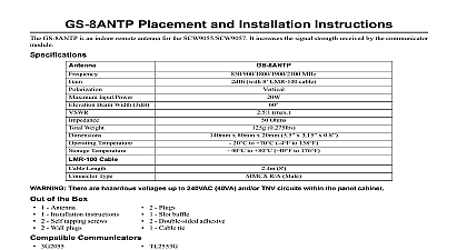
GS 15 25 50ANTQ Placement and Installation Instructions Type Frequency Bands Beamwidth Beam width 3dB max Weight inc Cable lb kg Length Diameter inch mm Cable Length ft m type Cable Length inch types Dipole 850 1900 Ohms 0.37kg 4.5m Male Dipole Dipole low high band low high band 850 1900 850 1900 ohms 1kg 7.6m Male ohms 2.3kg 15.2m Male 0.46 12mm 0.79 20mm 0.79 20mm Female to MMCX Male SMA Female to MMCX Male Female to MMCX Male A PANEL FOR GS INSTALLATION the TL260GS GS2060 There are HAZARDOUS VOLTAGES up to 240VAC 40VA and or TNV circuits within the panel cabinet down the system the supplied white whip antenna from the panel cabinet by rotating the base of the antenna anti clockwise the brass nut holding the threaded section remains and is tight the cabinet front cover to allow visibility of the green signal strength LEDs on the communicator board the free cable end of the extension antenna onto the extension antenna screw down the rubber sleeve on the extension antenna cable over the connection point see picture up the unit by connecting at the mains strength LEDs with antenna removed nut TL260 fitting cable sleeve Extension antenna connected These instructions shall be used in conjunction with the TL260GS TL265GS GS2060 GS2065 Instal Manual Disconnect power and telephone lines during the installation of the GS 15ANTQ GS 25ANTQ GS 50ANTQ antennas The GS 15ANTQ GS 25ANTQ and GS 50ANTQ antennas shall be used only in con with the supplied coaxial cable The GS 15ANTQ GS 25ANTQ and GS 50ANTQ antennas shall be by service persons only Use caution when installing the GS 25ANTQ and GS 50ANTQ antennas near lines The outside antenna system should not be located in the vicinity of overhead power lines or electric light or power circuits or where it can fall into such power lines or circuits as contact with might be fatal NEVER install the antenna during a lightning storm When installation is complete ver that the mounting is secure and the connector is properly attached Ensure the antenna installation is the TL265GS GS2065 the front cover of the panel power to the panel by disconnecting the mains and disconnecting the back up battery by removing the RED con from the battery the extension antenna plug cap located on the top right of the panel enclosure the existing PCB antenna cable from the communicator in the following sequence the cable from the radio module by inserting a small flat head screwdriver between the cable and the radio mod then gently pry the plug loose Use a pair of pliers to grip the head of the cable connector closest to the PCB antenna and pull away from the board Note other method for removal of this connector may cause permanent damage to the on board connector the 12.7cm 5 antenna cable supplied in the antenna kit the small plug end of the cable into the radio module and push firmly to ensure the cable connector fully engages the brass nut and washer from the other end of the cable and insert the screw thread through the hole in the top right the panel the washer and nut on the screw thread and tighten it with your fingers the free cable end of the extension antenna onto the threaded brass connector that exits the top right of the panel Ensure the connection is tight down the rubber sleeve on the extension antenna cable over the connection point the battery RED connector up the unit by reconnecting it at the mains plug cap location Removing cable end 1 cable end 2 near PCB antenna jumper cable and brass nut cable sleeve antenna connected to the TL265GS GS2065 PLACEMENT AND INSTALLATION INSTRUCTIONS GS 15ANTQ is an indoor remote antenna that offers the ability to increase the signal strength received by the TL260GS module by positioning the antenna in a place where the field strength is stronger Antenna Placement Test choose a suitable location for the GS 15ANTQ an antenna placement test should be performed an antenna placement test by moving the antenna around to determine the location which exhibits the highest signal The relative signal strength is indicated on the green LEDs See the TL260GS TL265GS GS2060 GS2065 installation manual more details about how to read the signal strength indication LEDs The TL260GS TL265GS GS2060 GS2065 does not need to be activated to show the signal strength indication just powered regarding antenna placement antenna must only be used indoors the antenna away from possible sources of electrical interference antenna must be mounted in a vertical orientation to obtain optimal signal strength the signal strength is poor try relocating the antenna left or right up or down by a factor of a few inches Antenna Installation installing the GS 15ANTQ to the proposed location please consider the following points Make sure the antenna is in a physically secure location to avoid tampering the antenna is mounted vertically the bracket to the wall using suitable screws the full length of the antenna cable supplied do not cut or splice the cable the cable with suitable cable clips at less than 1 spacing turning the cable through a 90 degree corner then ensure that the bend radius is more than 1 excess cable can be coiled close to the TL260GS TL265GS GS2060 GS2065 unit Do not over coil the cable ensure the coil is not less than 6 any long cable installation make sure the antenna cable does not place strain on the equipment Antenna Placement Confirmation the GS 15ANTQ antenna is connected to the TL260GS TL265GS GS2060 GS2065 module it should be retested in the pro location to verify the signal strength is acceptable PLACEMENT AND INSTALLATION INSTRUCTIONS GS 25ANTQ and the GS 50ANTQ are high gain external antennas that offer the ability to increase the signal strength received the TL260GS TL265GS GS2060 GS2065 module by mounting the antenna at a high elevation in a open air outdoor environment Antenna Placement Test choose a suitable location for the GS 25 50ANTQ an antenna placement test should be performed regarding antenna placement an antenna placement test by moving the antenna around to determine the location which exhibits the highest signal The relative signal strength is indicated on the green LEDs See the TL260GS TL265GS GS2060 GS2065 installation manual more details about how to read the signal strength indication The TL260GS TL265GS GS2060 GS2065 does not need to be activated to show the signal strength indication just powered Antenna Installation installing the GS 25 50ANTQ to the proposed location please consider the following points antenna is designed for outdoor use but can also be used indoors at high elevations antenna must always be mounted vertically the antenna as high as possible with a clear view around the antenna away from possible sources of electrical interference the signal strength is poor try to relocate the antenna left or right up or down by a factor of a few feet the antenna is mounted vertically active antenna element white fiberglass section should not be placed up against a wall or similar structure the bracket to the wall using suitable screws the base of the antenna firmly around the heat shrink area Be careful not to over tighten the bracket causing damage to antenna base the cable down to the intended location of the TL260GS TL265GS GS2060 GS2065 unit the full length of the antenna cable supplied do not cut or splice the cable the cable with suitable cable clips at less than 1 spacing