DSC HS-CAB2800 - Installation Manual - English - Concourse Cabinet

File Preview
Click below to download for free
Click below to download for free
File Data
| Name | dsc-hs-cab2800-installation-manual-english-concourse-cabinet-0726458913.pdf |
|---|---|
| Type | |
| Size | 901.00 KB |
| Downloads |
Text Preview
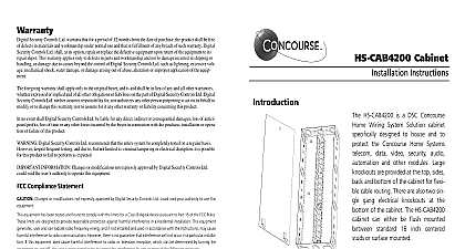
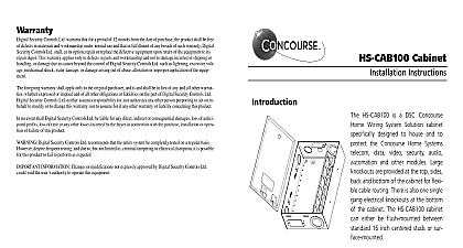
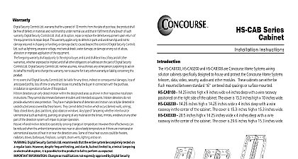
Warranty Security Controls Ltd warrants that for a period of 12 months from the date of purchase the product shall be free defects in materials and workmanship under normal use and that in fulfillment of any breach of such warranty Digital Controls Ltd shall at its option repair or replace the defective equipment upon return of the equipment to its depot This warranty applies only to defects in parts and workmanship and not to damage incurred in shipping or or damage due to causes beyond the control of Digital Security Controls Ltd such as lightning excessive volt mechanical shock water damage or damage arising out of abuse alteration or improper application of the equip foregoing warranty shall apply only to the original buyer and is and shall be in lieu of any and all other warranties expressed or implied and of all other obligations or liabilities on the part of Digital Security Controls Ltd Digital Controls Ltd neither assumes responsibility for nor authorizes any other person purporting to act on its behalf modify or to change this warranty nor to assume for it any other warranty or liability concerning this product no event shall Digital Security Controls Ltd be liable for any direct indirect or consequential damages loss of antici profits loss of time or any other losses incurred by the buyer in connection with the purchase installation or opera or failure of this product Digital Security Controls Ltd recommends that the entire system be completely tested on a regular basis despite frequent testing and due to but not limited to criminal tampering or electrical disruption it is possible this product to fail to perform as expected INFORMATION Changes or modifications not expressly approved by Digital Security Controls Ltd void the user authority to operate this equipment Cabinet Instructions HS CAB2800 is a DSC Concourse Wiring System Solution cabinet designed to house and to the Concourse Home Systems data video security audio and other modules Large are provided at the top sides and bottom of the cabinet for flexi cable routing There are also two sin gang electrical knockouts at the of the cabinet The HS CAB2800 can either be flush mounted standard 16 centered or surface mounted Home Systems is a division of Digital Security Controls Ltd Digital Security Controls Ltd Canada www dsc com in Canada 29034481 R002 of Package 1 1 1 2 door covers 28.5in 724mm 14.25in 362mm 29.6in 752mm 15.3in 389mm Instructions Choose a location where the temperature will not drop below 0 or go above 50 where the humidity will not create condensate on the cabinet or on the installed Locating the cabinet in a garage attic or damp basement is not recom the cabinet in an easily accessed location for service and future upgrades and 2 feet of a 110VAC outlet Alternatively the outlet may be located in the bot of the cabinet using the provided knockout s limitations regarding cabinet locations please consult local electrical and build codes Installation installation between 2 x 4 or larger studs on 16 centers 14.25 opening the cabinet between the studs with the front of the cabinet protruding to level of the finished wall and allowing for front cover installation For example if drywall is to be used extend the cabinet at least 5 8 past the studs Hold the in place and mark the position of the four pull out mounting tabs Set the cabinet down and drill pilot holes for the four mounting screws Place the cabinet in position and secure with the screws 6 x pan head wood Remove knockouts as required and install cable protection grommets not supplied not supplied the holes Installation installation will be on plywood backboard a plywood backboard to the wall studs using three 10 x 2 wood not supplied per side Allow sufficient clearance for the cabinet and access the knockouts Position the cabinet at a suitable height and mark the location of the upper mount holes Set the cabinet down and drill pilot holes for the upper mounting screws the upper mounting screws 6 x pan head wood screws not supplied do not fully tighten Hang the cabinet on the upper mounting screws mark the knockout holes and the mounting screw locations Remove the cabinet and cut the cable access holes in the plywood removing any edges cable protection grommets not supplied in the holes in the back of the cabi Hang the cabinet on the upper mounting screws install the bottom mounting 6 x pan head wood screws not supplied and tighten the upper mount screws Remove other knockouts as required and install cable protection grommets not sup in the holes Instructions cables are low voltage or communications cables Observe good wiring practices and according to appropriate wiring codes Maintain proper separation of these cables 110 220VAC power cables and use proper cable management and labeling tech all cables into the cabinet through the raceway Allow sufficient length at both of the run to avoid stress and for proper termination and trim out Label each cable both ends for easier identification and secure all cables complying with applicable codes Use good wiring prac to avoid damage during construction to module installation instructions for specific wiring and termination practices for application requirements for installation of CAT5 and coaxial cable should be met for proper of connected equipment Do not strip off cable sheathing more than required proper termination Do not kink or knot cable Do not crush cable with cable ties Do splice cable Do not bend cable at right angles or make any other sharp bends All bends should have a minimum of a 2 radius Do not untwist CAT5 pairs more 1 DSC recommends that two CAT5 and two RG6 cables be run to location for future applications even if they will not be terminated at cabinet or the outlet at this time 2 Refer to security system installation instructions for wiring and requirements for these systems Outlets for two single gang electrical boxes have been made in the bottom of the cab These may be used to provide 110VAC outlets to connect power supplies for ampli hubs security systems etc multiple outlets may be located outside of the cabinet but within two feet the cabinet to allow for short power supply cords for a grounding strap is an integral part of the cabinet The hole for a ground screw is located in the bottom of the cabinet Switch Installation for a tamper switch is an integral part of the cabinet The bracket for a tamper is located at the top of the cabinet Install the tamper switch according to the instructions included with the switch Installation Slide the tabs at the bottom of the door into the openings provided in the bottom of the lockset into the opening provided at the top of the door cabinet Push the top of the door towards the cabinet until fully closed the key into the lock and turn clockwise to lock the cabinet