DSC HS-VH1800 - Installation Manual - English - Concourse Passive 1x8 Video Splitter

File Preview
Click below to download for free
Click below to download for free
File Data
| Name | dsc-hs-vh1800-installation-manual-english-concourse-passive-1x8-video-splitter-6149582307.pdf |
|---|---|
| Type | |
| Size | 748.64 KB |
| Downloads |
Text Preview
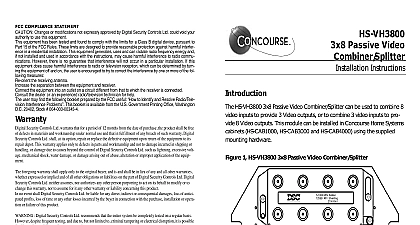
Warranty Security Controls Ltd warrants that for a period of 12 months from the date of purchase the product shall be free defects in materials and workmanship under normal use and that in fulfillment of any breach of such warranty Digital Controls Ltd shall at its option repair or replace the defective equipment upon return of the equipment to its depot This warranty applies only to defects in parts and workmanship and not to damage incurred in shipping or or damage due to causes beyond the control of Digital Security Controls Ltd such as lightning excessive volt mechanical shock water damage or damage arising out of abuse alteration or improper application of the equip foregoing warranty shall apply only to the original buyer and is and shall be in lieu of any and all other warranties expressed or implied and of all other obligations or liabilities on the part of Digital Security Controls Ltd Digital Controls Ltd neither assumes responsibility for nor authorizes any other person purporting to act on its behalf to or to change this warranty nor to assume for it any other warranty or liability concerning this product no event shall Digital Security Controls Ltd be liable for any direct indirect or consequential damages loss of antici profits loss of time or any other losses incurred by the buyer in connection with the purchase installation or opera or failure of this product Digital Security Controls Ltd recommends that the entire system be completely tested on a regular basis despite frequent testing and due to but not limited to criminal tampering or electrical disruption it is possible this product to fail to perform as expected INFORMATION Changes or modifications not expressly approved by Digital Security Controls Ltd void the user authority to operate this equipment Compliance Statement Changes or modifications not expressly approved by Digital Security Controls Ltd could void your authority to use this equipment has been tested and found to comply with the limits for a Class B digital device pursuant to Part 15 of the FCC Rules limits are designed to provide reasonable protection against harmful interference in a residential installation This equipment uses and can radiate radio frequency energy and if not installed and used in accordance with the Instructions may cause interference to radio communications However there is no guarantee that interference will not occur in a particular installa If this equipment does cause harmful interference to radio or television reception which can be determined by turning the on and off the user is encouraged to try to correct the interference by one or more of the following measures the receiving antenna the separation between the equipment and receiver the equipment into an outlet on a circuit different from that to which the receiver is connected the dealer or an experienced radio TV technician for help user may find the following booklet prepared by the FCC useful to Identify and Resolve Radio Television Interference Prob This booklet is available from the U S Government Printing Office Washington D C 20402 Stock 004 000 00345 4 device complies with Part 15 of the FCC Rules Operation is subject to the following two conditions 1 This device may not harmful interference and 2 this device must accept any interference received including interference that may cause undes operation Home Systems is a division of Digital Security Controls Ltd Digital Security Controls Ltd Canada www dsc com in Canada 29034468 R001 Passive Video Module Instructions HS VH1800 is a 1 x 8 passive video module on a mounting plate for use with the Concourse Home Wiring Systems Solution The passive video module is all ports passing APP with one CATV ANT input and eight outputs for multi room signal distribution The passive video module can also be used as an 8 input to output video combiner x 8 Video Module on a mounting plate of Package 1 Splitter MHz Loss P to P Loss Shielding Passing 400 dB max dB min dB min 40 dB max dB min dB min Ohm dB ports 24VDC 500 mA 600 dB max dB min dB min 1000 dB max dB min dB min Instructions Select a suitable mounting location for the HS VH1800 module inside the cabinet upper left corner of the cabinet is recommended Align the mounting tabs with the slots in the wire raceway and insert See Figure 1 Snap the module into place by pushing the opposite side towards the back of the requirements for installation of coaxial cable should be met for proper operation of connected Do not strip off cable sheathing more than required for proper termination Do not kink or cable Do not crush cable with cable ties Do not bend cable at right angles or create any other bends All cable bends should have a minimum of a 2 radius Attach RG6 style connectors to the incoming CATV ANT service and internal video cables Connect the terminated incoming service and internal mod cables to the red terminals on the passive video module Make up an RG6 patch cord of sufficient length to connect the red terminal of HS VH1800 to the black terminal of the HS VH400 or another HS VH1800 to the white terminal of the HS VA800 All drops to outlets will terminate the black terminals of the HS VH400 or HS VH1800 or at the white terminals of the HS VA800 Terminate any unused terminals with a 75 Ohm terminator Test all connections to confirm proper installation and termination Instructions Incoming Service Cable Route the incoming service cables into the cabinet through the raceway to the HS Module Allow sufficient length at both ends of the run to avoid stress and termination and trim out Attach an RG6 style connector to each incoming service cable Connect the ter incoming service cable to the black terminal Test all connections to confirm proper installation and termination Outlet Cables Home run RG6 coax cable to each desired outlet location and route the cables into cabinet through the raceway to the HS VH1800 module Allow sufficient length both ends of the run to avoid stress and for proper termination and trim out Label cable run at both ends for easier identification Terminate each RG6 drop at the desired outlet location using an RG6 style Attach the connector to an RG6 style jack and trim out using the wall plate If using a multiple outlet wall plate mark the jack accordingly Terminate each RG6 drop at the HS VH1800 module using an RG6 style connec Connect the terminated drops to the black terminals Terminate any unused terminals with a 75 Ohm terminator Test all connections to confirm proper installation and termination Video Module as Combiner used with an HS VH400 another HS VH1800 or an HS VA800 video module the splitter of the HS VH1800 can be used to combine and distribute external CATV and internal e g CCTV video signals Route the incoming CATV ANT service cable s into the cabinet through the raceway the HS VH1800 Allow sufficient length at both ends of the run to avoid stress and proper termination and trim out Route the incoming modulated internal video cable s into the cabinet through the to the HS VH1800 module Allow sufficient length at both ends of the run to stress and for proper termination and trim out