DSC HS-VT1680 - Installation Manual - English - Concourse 1x6 Analog Bridged Telecom Expansion Module With 1x8 Passive Video Splitter

File Preview
Click below to download for free
Click below to download for free
File Data
| Name | dsc-hs-vt1680-installation-manual-english-concourse-1x6-analog-bridged-telecom-expansion-module-with-1x8-passive-video-splitter-8195470362.pdf |
|---|---|
| Type | |
| Size | 796.48 KB |
| Downloads |
Text Preview
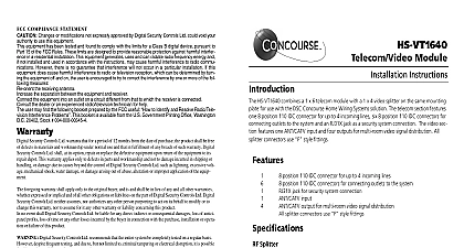
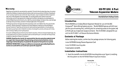
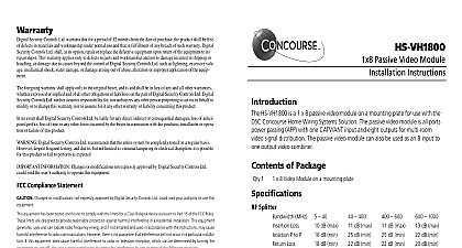
Warranty Security Controls Ltd warrants that for a period of 12 months from the date of purchase the shall be free of defects in materials and workmanship under normal use and that in fulfillment any breach of such warranty Digital Security Controls Ltd shall at its option repair or replace the equipment upon return of the equipment to its repair depot This warranty applies only to in parts and workmanship and not to damage incurred in shipping or handling or damage due to beyond the control of Digital Security Controls Ltd such as lightning excessive voltage shock water damage or damage arising out of abuse alteration or improper application of equipment foregoing warranty shall apply only to the original buyer and is and shall be in lieu of any and all warranties whether expressed or implied and of all other obligations or liabilities on the part of Security Controls Ltd Digital Security Controls Ltd neither assumes responsibility for nor any other person purporting to act on its behalf to modify or to change this warranty nor to for it any other warranty or liability concerning this product no event shall Digital Security Controls Ltd be liable for any direct indirect or consequential dam loss of anticipated profits loss of time or any other losses incurred by the buyer in connection the purchase installation or operation or failure of this product Digital Security Controls Ltd recommends that the entire system be completely tested on regular basis However despite frequent testing and due to but not limited to criminal tampering or disruption it is possible for this product to fail to perform as expected INFORMATION Changes or modifications not expressly approved by Digital Secu Controls Ltd could void the user authority to operate this equipment COMPLIANCE STATEMENT Changes or modifications not expressly approved by Digital Security Controls Ltd void your authority to use this equipment equipment has been tested and found to comply with the limits for a Class B digital pursuant to Part 15 of the FCC Rules These limits are designed to provide reasonable against harmful interference in a residential installation This equipment generates and can radiate radio frequency energy and if not installed and used in accordance with instructions may cause harmful interference to radio communications However there is guarantee that interference will not occur in a particular installation If this equipment does harmful interference to radio or television reception which can be determined by turn the equipment off and on the user is encouraged to try to correct the interference by one more of the following measures the receiving antenna the separation between the equipment and receiver the equipment into an outlet on a circuit different from that to which the receiver connected the dealer or an experienced radio TV technician for help user may find the following booklet prepared by the FCC useful to Identify and Radio Television Interference Problems This booklet is available from the U S Gov Printing Office Washington D C 20402 Stock 004 000 00345 4 device complies with Part 15 of the FCC Rules Operation is subject to the following two 1 This device may not cause harmful interference and 2 this device must any interference received including interference that may cause undesired operation requirements for installation of CAT5 cable should be met for proper operation of connected Do not strip off cable sheathing more than required for proper termination Do not or knot cable Do not crush cable with cable ties Do not bend cable at right angles or create other sharp bends All cable bends should have a minimum of a 2 radius Do not untwist pairs more than 1 2 inch requirements for installation of coaxial cable should be met for proper operation of connected Do not strip off cable sheathing more than required for proper termination Do not or knot cable Do not crush cable with cable ties Do not bend cable at right angles or make other sharp bends All cable bends should have a minimum of a 2 radius telecom module is intended for use with analog telephones and POTS Plain Old Telephone Any other use may cause improper operation of the connected equipment All IDC con except IDC 1 Telephone Line In are connected in parallel and therefore output connec can be made at any IDC connector Input lines 2 3 and 4 are connected in parallel to all of IDC connectors Line 1 is designed for use with RJ 31X connector and is connected in parallel the IDC connectors when no RJ 31X plug is in the jack Home Systems is a division of Digital Security Controls Ltd Digital Security Controls Ltd Canada www dsc com in Canada 29034467 R001 Telecom with Passive APP Video Combo Module Instructions HS VT1680 is a 1 x 6 telecom module combined with 1 x 8 passive video on one mounting plate for use with the DSC Concourse Home Wiring Solution The telecom section features one 110 IDC connector for up to incoming lines six 110 IDC connections for connecting outlets to the system an RJ 31X Jack on line 1 as a security system connection The passive video is all ports power passing APP with one CATV ANT input and eight out for multi room video signal distribution The passive video module can also used as an 8 input to one output video combiner All connectors use style of Package 1 1 x 8 Video Module on a mounting plate 1 1 x 6 Telecom Card 7 plastic standoffs Splitter MHz 40 400 600 1000 Loss dB max dB max dB max dB max P to P dB min dB min dB min dB min dB min dB min dB min dB min Loss Shielding Ohm dB Passing ports 24VDC 500 mA Module Input Lines 4 max Wiring Standard T568A Connections 6 Interfaces RJ 31X Line 1 Connection 110 Style IDC Connection 110 Style IDC Out Connection None Security Panel Connection RJ 31X jack is provided on Line 1 for a security panel connection Follow the Instructions included with the security system for proper connection the RJ 31X jack Instructions are two sets of holes in the mounting plate that will accomodate telecom module use the set of holes located nearest the positioning Insert the standoffs 7 into the mounting plate to match the hole on the telecom distribution module Refer to figure 1 Align the telecom distribution module over the stand offs and snap into Choose a suitable mounting location for the HS VT1680 module inside cabinet The upper left corner of the cabinet is recommended Align the two mounting tabs with the slots in the wire raceway and the module Align the locating pin with the hole in the cabinet and snap module into Instructions Service Cables the incoming telephone service cable s into the cabinet through raceway to the HS VT1680 module Allow sufficient length at both of the cable run to avoid stress and to permit proper termination trim out the incoming telecom service cable s at the telephone line in labeled IDC 1 using a 110 punchdown tool Line 1 termi at L1 Line 2 at L2 Line 3 at L3 and Line 4 at L4 See Figure 1 the incoming video service cable into the cabinet through the to the HS VT1680 module Allow sufficient length at both ends the cable run to avoid stress and to permit proper termination and out Attach an RG6 style connector to the incoming service cable Con the terminated incoming service cable at the terminal marked See Figure 1 all connections to confirm proper installation and termination Cables Home run CAT5 cable to each desired telecom location and route the