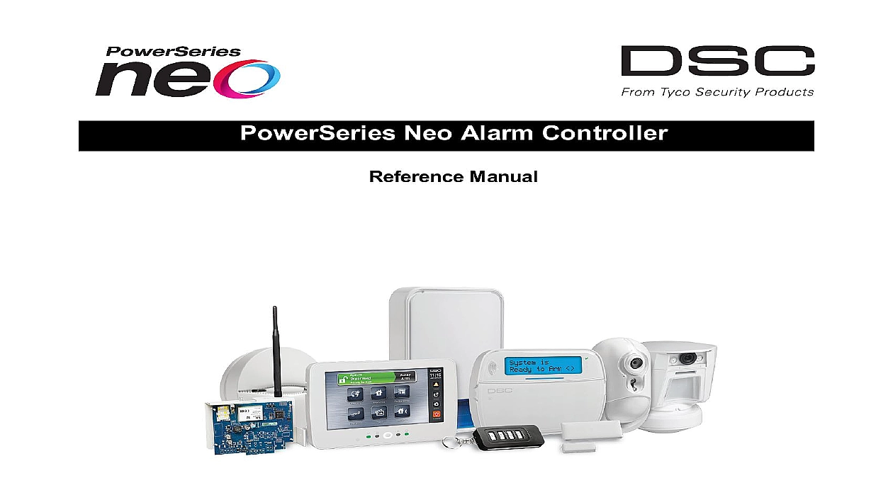
DSC HS2016-HS2032-HS2064-HS2128 - V1 3 - Reference Manual - Eng - R002 (INT)

File Preview
Click below to download for free
Click below to download for free
File Data
| Name | dsc-hs2016-hs2032-hs2064-hs2128-v1-3-reference-manual-eng-r002-int-5732618049.pdf |
|---|---|
| Type | |
| Size | 5.05 MB |
| Downloads |
Text Preview
PowerSeries Neo Alarm Controller Manual E E This manual contains information on limitations regarding product use and function and information on the lim as to liability of the manufacturer The entire manual should be carefully read Instructions for Service Personnel When using equipment connected to the telephone network always follow the basic safety instructions provided this product Save these instructions for future reference Inform the end user of the safety precautions that must be when operating this equipment Installing The Equipment your package includes the following items and User manuals including the SAFETY INSTRUCTIONS and SAVE these instructions all WARNINGS AND INSTRUCTIONS specified within this document and or on the equipment HS2016 4 HS2016 2032 2064 2128 alarm controller Power Supply direct plug in Mounting hardware A Suitable Location For The Alarm Controller the following list as a guide to find a suitable location to install this equipment Locate near a telephone socket and power outlet Select a location free from vibration and shock Place alarm controller on a flat stable surface and follow the installation instructions NOT locate this product where people may walk on the secondary circuit cable s NOT connect alarm controller to electrical the same circuit as large appliances NOT select a location that exposes your alarm controller to direct sunlight excessive heat moisture vapors chemicals or dust NOT install this equipment near water e g bath tub kitchen laundry sink wet basement near a swimming pool NOT install this equipment and accessories in areas where risk of explosion exists NOT connect this equipment to electrical outlets controlled by wall switches or automatic timers interference sources installing equipment near heaters air conditioners ventilators and refrigerators locating equipment close to or on top of large metal objects e g wall studs Locating Detectors and Escape Plan on page 220 for information on locating smoke and CO detectors Precautions Required During Installation NEVER install this equipment and or telephone wiring during a lightning storm NEVER touch uninsulated telephone wires or terminals unless the telephone line has been disconnected at the net Position cables so that accidents can not occur Connected cables must NOT be subject to excessive mechanical interface Use only the power supply provided with this equipment Use of unauthorized power supplies may cause damage For direct plug in versions use the transformer supplied with the device THIS EQUIPMENT HAS NO MAINS ON OFF SWITCH THE PLUG OF THE DIRECT PLUG IN POWER SUPPLY IS INTENDED SERVE AS THE DISCONNECTING DEVICE IF THE EQUIPMENT MUST BE QUICKLY DISCONNECTED IT IS IMPERATIVE THAT TO THE MAINS PLUG AND ASSOCIATED MAINS SOCKET OUTLET IS NEVER OBSTRUCTED NOTE FOR EU AUS NZ equipment is stationary fixed and must be installed by Service Persons only Service Person is defined as a person hav the appropriate technical training and experience necessary to be aware of hazards to which that person may be in performing a task and of measures to minimize the risks to that person or other persons It must be installed and within an environment that provides the pollution degree max 2 over voltages category II in non hazardous indoor loc only When using equipment connected to the mains and or to the telecommunication network there are basic safety that should always be followed Refer to the safety instructions provided with this product and save them for reference To reduce the risk of fire electric shock and or injury observe the following Do not attempt to service this yourself Opening or removing the cover may expose you to dangerous voltage or other risk Refer servicing to qual service persons Never open the device yourself Use authorized accessories only with this equipment DO NOT leave deposit ANY object on the top of the cabinet of this equipment The cabinet as it is installed on the wall is not to support any supplementary weight Do not spill any liquids on the cabinet Do not touch the equipment and its cables during an electrical storm there may be a risk of electric shock Never touch uninsulated wires or 2 unless the equipment has been disconnected from the mains supply and from the telecommunication network that cables are positioned so that accidents cannot occur Connected cables must not be subject to excessive mech strain Do not spill any type of liquid on the equipment Do not use the Alarm system to report a gas leak if the system near a leak Do not subject the connected cables to an excessive mechanical strain These safety instructions should not you from contacting the distributor and or the manufacturer to obtain any further clarification and or answers to your 3 1 Introduction About the System 2 Installation Overview of Installation Process Alarm Controller Installation Wiring Installing Modules 3 Configuration Basic Configuration Steps Using the Keypad Enrollment Working with Partitions Trouble Indicators Keypad Partition Setup Alternate Communicator Setup Local Firmware Upgrade Testing the System 4 System Operation Arming and Disarming Partition vs Global Keypad Labels Annunciation Keypad Function Keys Language Selection Commands SMS Command and Control Visual Verification 5 Programming How to Program Programming Methods Programming Descriptions 6 Programming Worksheets Label Programming Zone Setup System Times Access Codes PGM Programming System Lockout System Options Auto Arm Disarm Partition and Zone Assignment Communications Call Directions 4 DLS Programming Virtual Inputs Schedule Programming Audio Module Programming Wireless Programming Alternate Communicators Keypad Programming Template Programming System Information Module Programming Wireless Placement Testing Battery Settings Restoring Factory Defaults 7 Troubleshooting Testing Troubleshooting 1 Reporting Codes 2 Word Library 3 Template Programming Tables 4 Regulatory Approvals SIA False Alarm Reduction Installations Quick Reference Australia New Zealand Regulatory Compliance Mark New Zealand Telepermit Grant 5 ASCII Characters 6 Wiring Diagrams 7 Specifications Index Neo Reference Manual Feature Changes 5 1 Introduction About the System PowerSeries Neo alarm panel is a feature rich scalable alarm system designed for residential and light commercial The alarm panel supports both hardwired and wireless devices This section lists the features of the alarm panel avail models and compatible devices following symbols are used to indicate features or methods of operation that are only available in a particular market No indicates the feature or operation is available for all markets unless noted specifically otherwise North America Europe France United Kingdom Features following features are available on the PowerSeries Neo alarm controller Wireless Keypads Wireless Keys Panic Pendants and Proximity Tags 16 32 64 or 128 wireless or hardwired zones supported including 6 or 8 hardwired zones available on the con 40 zone types and 14 programmable zone attributes Up to 16 separate wireless keypads supported Up to 32 separate wireless keys or supported Up to 94 separate proximity tags supported Codes Up to 1002 access codes 1000 level 2 EN including one system master code level 3 EN In addition one installer level 3 EN and one maintenance code are available EN50131 1 compliant systems using 1000 access codes shall set the access code to 8 digits section 041 02 Programmable attributes for each user code see Access Code Attributes on page 49 Outputs PGMs Up to 4 programmable outputs PGM on the alarm controller with 49 available options 22 38 80 148 maximum programmable outputs Supervision Features PowerSeries Neo continuously monitors a number of possible trouble conditions and provides audible and visual indic at the keypad Trouble conditions include AC power failure Zone trouble Fire trouble Telephone line trouble Communicator trouble Low battery condition RF jam AUX power supply fault Failure to communicate Module fault supervisory or tamper


