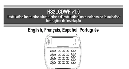
DSC HS2LED-LCD (P)(RF)x Installation Guide v1 0 - R001 EN-FR-ES-PO

File Preview
Click below to download for free
Click below to download for free
File Data
| Name | dsc-hs2led-lcd-p-rf-x-installation-guide-v1-0-r001-en-fr-es-po-5213079684.pdf |
|---|---|
| Type | |
| Size | 3.42 MB |
| Downloads |
Text Preview
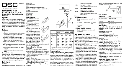
HS2LED HS2ICN P RF x HS2LCD RF P x v1.0 Instructions Instructions d Instrucciones de instalaci de Instala Fran Espa Portugu Refer to the PowerSeries Neo Reference manual for information on limitations regarding product use and function and information on the limitations as to the liability of the manufacturer These instructions must be used in conjunction with the system installation manual of the control panel with which this equipment is intended to be used This installation sheet applies to the fol models HS2LED HS2ICN HS2ICNP HS2ICNRFx HS2ICNRFPx HS2LCD HS2LCDP HS2LCDRFx and HS2LCDRFPx x 9 where the system operates in 912 919MHz 8 where the operates in 868MHz band and 4 where the system operates in 433MHz band The Model HS2LED HS2LCD P HS2ICN P HS2LCDRF P 8 HS2ICNRF P 8 keypads have been certified by according to EN50131 1 2006 A1 2009 EN50131 3 2009 for Grade 2 Class II Instructions HS2LED HS2ICN P RF x HS2LCD RF P x keypads are with the PowerSeries Neo HS2016 32 64 HS2014 and HS2128 panels The RF keypads combine a wireless with the respective HS2 keypad Model not UL ULC listed Temperature range 10 to 55 14 to 131 Tem range for UL ULC 0 to 49 32 to 120 Humidity MAX 93 R H non condensing Plastic enclosure protection degree IP30 IK04 Voltage rating 13.8VDC nominal power provided by the control panel Connects to control panel Corbus via 4 wires 1 configurable zone input or PGM output HS2LED HS2ICN P HS2LCD P HS2ICNRF P Current draw 55mA min 105mA max Wall mount tamper 5 programmable function keys Ready Green LED Armed Red LED Trouble Yellow AC Green LED Dimensions L x W x D 168mm x 122mm x 20 mm Weight 260g Low temperature sensor Frequency 433 MHz HS2ICNRF4 HS2LCDRF4 868 MHz HS2ICNRF8 HS2LCDRF8 912 919MHz HS2ICNRF9 HS2LCDRF9 Up to 128 wireless zones Zone not to be programmed as Fire type or 24h type Keypads contain no serviceable parts Only models operating in band 912 919MHz are UL listed keypad package includes the following 1 keypad 4 mounting screws 2 end of line resistors Keypad inner door 1 keypad 4 mounting screws 2 end of line resistors Keypad inner door labels 1 tamper switch 1 tamper switch Installation Instructions Installation Instructions Mini Proximity prox 1 Compatible Devices PG smoke detector PG smoke and heat detector PG CO detector PG PIR motion detector PG PIR camera motion detector PG curtain motion detector PG dual tech motion detector PG mirror motion detector PG outdoor motion detector PG glass break detector PG shock detector PG flood detector PG temperature detector indoor temperature probe requires PGx905 PGTEMP PG key PG key PG panic key PG 2 button key PG indoor siren PG outdoor siren PG repeater PG door window contact PG door window contact w AUX In this chart x in the model number represents the frequency of the device as follows 9 912 919 MHz 868MHz 4 433MHz Only models operating in the band 912 919 MHz are or cUL listed where indicated Only UL approved are to be used with UL ULC listed systems the keypad where it is accessible to designated points of and exit Once a dry and secure location is selected per the following steps to mount the keypad Keypad Insert the tip of a flat head screwdriver into the slots at the left and right of the keypad Gently pry open the faceplate This will remove it and allow for mounting and Wire Keypad holes slot holes Secure keypad to wall using mounting holes Use all four provided unless mounting on a single gang box Use plastic anchors supplied if the unit is to be mounted on with a screw If using the keypad tamper secure the tamper plate to the For UL ULC listed commercial burglary installations use of the keypad tamper is mandatory Run wire through wiring slot or knockouts Connect Corbus PGM Zone wiring to keypad Place tamper switch into hole on backplate Place keypad into backplate ensuring the wire is pushed into the wall as much as possible Route the wire inside keypad ensuring high components are avoided Snap the assembly closed ensuring that there is no pressure to keypad from the wire below If any tension is found between the front keypad assem and the wiring open the keypad reroute the wire and close Repeat these steps until the keypad is closed properly Before wiring the unit ensure all power AC and battery is discon from the control panel Connect the four Corbus wires the control panel red yellow and green to keypad terminals Refer to diagram RED R BLK B YEL Y GRN G zone or P Z output If programmed as an input a such as a door contact may be connected to the terminal of the keypad This the need to run wires back to the control panel for device To connect the zone run one wire from the device the terminal and the other wire from the device to the black terminal For powered devices run the red wire to R positive terminal and the black wire to the B nega terminal When using end of line supervision connect zone according to one of the configurations described in PowerSeries Neo Reference manual For UL ULC installations the zone input is a supervised SEOL DEOL The supervision resistor is 5600 If no EOL is used there is a three foot maximum distance for the connected device Use only in conjunction with listed devices This initiating device connected to this input contact is to be used for medical or fire applications If the terminal is programmed as an output a small such as DSC model RM 1 or RM 2 or buzzer or other operated device may be connected between the positive voltage and the terminal max load is 50mA For UL ULC listed installations use UL ULC listed Power all wiring is complete and the equipment is secured to the structure with at least two screws apply power to the panel Connect the battery leads to the battery Connect the AC transformer more information on control panel power specifications see PowerSeries Neo Reference manual the Keypad Press 8 Installer Code Use the keys to navigate through the menus or jump to a specific section by entering the section number To input data use the keys to select a character then the keypad button for the number letter Using the keys scroll to the next character and repeat procedure For information on entering HEX data refer to PowerSeries Neo Reference manual name Y N Romanian Russian Latvian Lithuanian Ukrainian Slovak Serbian Estonian Slovenian German Swedish Norwegian 22 Bulgarian Danish Hebrew Greek Turkish FFU Croatian Hungarian Programming 000 000 Enter the two digit number corresponding to the desired 2 Languages English Spanish Portuguese French Italian Dutch Polish Czech Finnish the Keypad can be enrolled automatically or manually In either case serial number of the device is used as an identifier If there is no keypad enrolled on the system once you up the keypad will display the message Press any key to Other keypads can then be enrolled from the first keypad one of the following enrollment options

