DSC Install Manual - PTK5507 - 29008073R001
File Preview
Click below to download for free
Click below to download for free
File Data
| Name | dsc-install-manual-ptk5507-29008073r001-1340598672.pdf |
|---|---|
| Type | |
| Size | 1.24 MB |
| Downloads |
Text Preview
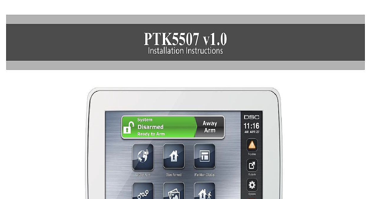
PTK5507 v1.0 Instructions Please refer to the System Installation Manual for information on limitations regarding product use and function and information on the limitations as to liability of the manufacturer These instructions shall be used in conjunction with the system Installation Manual of the Control Panel with which this equipment is intended to be used Instructions PTK5507 keypad can be used on security systems with to 64 zones These keypads are compatible with the lat version of the Power Series V4.2 security systems Temperature range 10 to 55 14 to 131 Humidity MAX 93 R H non condensing Plastic enclosure protection degree IP30 IK04 touchscreen Voltage rating 12VDC nominal Connects to control panel via 4 wire Keybus Keybus distance 60 m 200 ft max keybus distance in power mode 33.5 m 110 ft Up to 8 keypads per system PTK5507 Current draw 200 mA standby 300 mA acti 400mA Extra Power Mode Wall mount tamper 5 programmable function keys Ready Green LED Armed Red LED Trouble Yellow LED AC LED Touchscreen display 8.5 x 5.1 x 0.8 127.9 mm L x 195 W x 20.35 mm D SD card slot holds any standard Secure Digital SD card 32 x x 2.1 mm containing photos Wiring standard four wire connection Viewing angle horizontal viewing angle 50 typ Vertical viewing angle 70 top 70 bottom typ Brightness 280 cd m2 Power keypad package includes the following parts Power keypad mounting screws anchors for wall mounting tamper switch Instructions Manual should mount the keypad where it is accessible to desig points of entry and exit Once you have selected a dry secure location perform the following steps to mount keypad and Wire Keypad Remove the SD card before opening the touchscreen see 1 Disassembling the touchscreen without removing the card will damage the unit Remove screw at the bottom of the keypad Insert screwdriver into slots and pry up to remove cover 1 Removing the backplate card Secure keypad backplate to wall using mounting holes Figure 2 Use all 4 screws provided unless mounting a single gang box Use the plastic anchors supplied if unit is to be mounted on drywall If using the keypad secure the tamper plate to the wall with a screw 2 Mounting the backplate hole hole slot for hole hole Run wire through wiring slot Connect keybus wiring to see Wiring section Place keypad into backplate ensuring the wire is pushed into the wall as much as possible Route the wire the keypad ensuring high components are avoided the front assembly closed ensuring that there is no to the keypad from the wire below If any tension is found between the front keypad assembly wiring please open the keypad re route the wire and close Repeat these steps until the keypad is closed properly Before wiring the unit ensure that all power AC trans telecommunication network and battery is dis from the control panel Wrap the Keybus wires through the ferrite core see Figure one turn is enough The ferrite core shall be installed as to the touchscreen as the installation will allow 3 Ferrite core Connect the four Keybus wires from the control panel yellow black and red to the keypad terminals to Figure 4 4 Wiring USED Power all wiring is complete and the equipment is secured to building structure with at least two screws apply power the control panel Connect the battery leads to the battery Connect the AC transformer Connect telecommunication network more information on control panel power specifications the control panel Installation Manual Route all the wiring according to the local codes and the Keypad are sev program options are described below Programming the keypad is sim to programming the rest of the system When you are in keypad programming sections the keypad will display options are turned on To turn an option on or off the number corresponding to the option on the number The numbers of the options that are currently turned will be displayed For example if options 1 and 4 are the display will look like the diagram shown 4 Option information on programming the rest of your security please refer to your system Installation Manual Do not enable keypad blanking panel programming 016 option 3 If keypad blanking is enabled the panel stop sending out the status and the keypad status will be the Keypad keypad will need to be assigned to a partition and slot if or keypad zones are being used Keypad and keypad option programming must be done each keypad individually 1st digit of keypad assignment is used to determine assignment 1 to 8 If partitioning is not used 1 For Global Keypads enter 0 2nd digit of keypad assignment is used to determine assignment for keypad supervision Each keypad will be a different slot number from 1 to 8 the following at each keypad installed on the system Enter Installer Programming by pressing Options Installer Installer Code then Keypad Mode Prog Press 000 for keypad programming Press 0 for Partition and Slot Assignment Enter the 1st digit 0 to 8 for partition assignment Enter the 2nd digit 1 to 8 for slot assignment supervision Press the key twice to exit programming After assigning all keypads perform a supervisory reset by Options Installer Menu Installer Code 902 waiting for 60 seconds Press the key to exit programming after 60 seconds Labels Enter Options Installer Menu Installer Code then Label Select the desired Label to Program Using the keyboard on the screen enter the new label and save when complete LCD Labels LCD programming is done per keypad If more than one keypad is present on the system labels programmed at keypad can be broadcast to all other LCD keypads Per the following procedure in order to broadcast labels 1 Program one LCD keypad completely 2 Make sure all LCD keypads are connected to the Keybus 3 Enter keypad programming by pressing Options Menu Installer Code Keypad Mode Prog then enter cid 2 998 cid 2 at the keypad that was programmed keypad will now broadcast all the information pro to all the other LCD keypads on the system 4 When the keypad is finished press the key to exit Characters Backlight Brightness Level Press Options Keypad Config then Backlight Use slide bar to adjust brightness to desired setting Press the Back or Home button the Buzzer Level Press Options Keypad Config then Buzzer Control Use slide bar to adjust buzzer to desired setting Press the Back or Home button Calibration Mode Press Options Keypad Config then Calibration Press the cross hairs on the screen to complete calibration Calibration mode can also be entered by pressing and the home button for 3 seconds the Background Image Press Options Installer Menu Installer Code Keypad Pro then Background Image Select image to use image from SD card as background To exit press Back or Home button Text Enable Disable Press Options Installer Menu Installer Code Keypad Programming then Options Select the desired text color by enabling or disabling Dark Text Disabling makes the text This feature affects only the text on the Classic Square Button Home Page Home Page Look Press Options Keypad Config Home Page Select the desired view from either classic look square or contemporary rondel To exit press the Back or Home button a Firmware Upgrade Insert an SD card in the PTK5507 with the new firmware Press Options Installer Menu Installer Code Keypad Programming then Firmware Select OK to perform a firmware update if a new firmware version is available Fire Auxiliary and Panic Buttons Press Options Installer Menu Installer Code Keypad Programming then Options Enable disable the desired Fire Auxiliary and Panic buttons The Fire Auxiliary and Panic buttons are enabled by default on the PTK5507 Power Option Extra Power option will increase t