DSC IT-120 v1 0 Integration Module INIS EN-FR-SP fm

File Preview
Click below to download for free
Click below to download for free
File Data
| Name | dsc-it-120-v1-0-integration-module-inis-en-fr-sp-fm-0493257816.pdf |
|---|---|
| Type | |
| Size | 658.48 KB |
| Downloads |
Text Preview
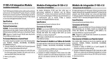
IT 120 v1.0 Integration Module Instructions d IT 120 v1.0 d IT 120 Integration Module can be used to quickly and easily with PowerSeries panels through a standard ethernet connection using Services for Devices Current Draw 120 mA Connections The 4 wire KEYBUS connection is used by the panel to with the module Connect the RED BLK YEL and terminals to the KEYBUS terminals on a PowerSeries panel Requires a CAT5 Ethernet cable Only the TXD TXD and RXD connections are used Connect Module to a Control Panel module should be installed in one of the following enclosures PC5003C or DSC Concourse cabinets see Fig A module to the KEYBUS with the panel powered down length must not exceed 33ft 10m the IT 120 Integration Module via a CAT5 cable to a or router located in the same room and no more than 30m from the IT 120 recommended up the system configure the unit please refer to the Exceptional EI Installation Manual IT 120 is intended to be installed by a certified EI only instructions shall be used in conjunction with the associated control panel of 1 Status Reporting via LED module d IT 120 peut utilis pour se communiquer et facilement avec les tableaux PowerSeries travers connexion standard de l RJ 45 utilisant for Devices en Courant du Module 120 mA du Terminal La connexion KEYBUS de 4 fils est utilis par le tableau se communiquer avec le module Connectez les bornes RED BLK NOIR YEL JAUNE et GRN VERT aux bornes KEYBUS un tableau PowerSeries Exige un c de l CAT5 Seulement suivants sont utilis TXD TXD RXD et RXD Connecter le Module un Tableau de Contr module doit install dans les bo de protection suivantes PC5003C ou des coffrets de DSC Concourse Fig A Connectez le module au KEYBUS avec le tableau d la de Keybus ne doit pas exc 10 m 33pieds Connectez le module d IT 120 travers d c au syst un concentrateur ou routeur Localis dans la salle et une distance maximale de 30m 98.4 pi du IT 120 recommand Branchez le syst Pour configurer IT 120 r au manuel d d doit uniquement par un module certifi par EI seulement Ces instructions doivent utilis en conjoint avec les d applicables du contr d 1 Rapports de status par LED is not powered is powered but communication panel is not initiated from start up module n pas aliment module est aliment mais la avec le tableau n pas depuis l every is powered and is receiving sending with panel 2 seconds off and second on is powered but there is a Trouble the Keybus connection chaque module est aliment et re donn avec le tableau clignote avec la de 2 secondes et seconde allum module est aliment mais il y a un avec le raccord Keybus de Integraci IT 120 v1.0 de Instalaci m de Integraci IT 120 puede utilizarse para comunicarse y f con los paneles PowerSeries a trav de una conexi est de Ethernet RJ 45 usando for Devices de Corriente del M 120 mA del Terminal La conexi KEYBUS de 4 hilos es utilizada por el panel comunicarse con el m Conecte los terminales RED BLK NEGRO YEL AMARILLO y GRN VERDE a los KEYBUS en un panel PowerSeries Requiere un cable de Ethernet CAT5 Solamente se utilizan conexiones siguientes TXD TXD RXD RXD Conectar el M a un Panel de Control m debe instalarse en una de las siguientes cajas de PC4003C PC5003C o las cajas met de DSC Fig A Conecte el m al KEYBUS con el panel apagado la del Keybus no debe exceder 10m 33 pie Conecte el M de Integraci IT 120 a trav de un cable a un concentrador o enrutador Localizado en la misma y a una distancia de no m que 30m 98.4 pi del m Encienda el sistema Para configurar el IT 120 refiera al manual de la instalaci de EI m IT 120 solamente debe instalarse por un instructor EI solamente instrucciones deben utilizarse en conjunto con las de Instalaci aplicables del controlador de PowerSeries 1 Informes del Status a trav del LED a cada pone intermitente con la de 2 segundos y segundo m no est alimentado m est siendo alimentado pero la con el panel no es iniciada la iniciaci m est siendo alimentado y est transmitiendo datos con el m est siendo alimentado pero un Problema con la conexi Keybus 9 0 0 7 3 5 0 R0 0 1 BLK YEL GRN Panel le Tableau Panel Center A COMPLIANCE STATEMENT Changes or modifications not expressly approved by Digital Security Controls could void authority to use this equipment equipment generates and uses radio frequency energy and if not installed and used properly in strict with the manufacturer instructions may cause interference to radio and television reception It been type tested and found to comply with the limits for Class B device in accordance with the specifi in Subpart B of Part 15 of FCC Rules which are designed to provide reasonable protection against interference in any residential installation However there is no guarantee that interference will not in a particular installation If this equipment does cause interference to television or radio reception can be determined by turning the equipment off and on the user is encouraged to try to correct the by one or more of the following measures Re orient the receiving antenna Relocate the alarm control with respect to the receiver Move the alarm control away from the receiver Connect the alarm control into a different outlet so that alarm control and receiver are on different circuits necessary the user should consult the dealer or an experienced radio television technician for additional The user may find the following booklet prepared by the FCC useful How to Identify and Radio Television Interference Problems This booklet is available from the U S Government Office Washington D C 20402 Stock 004 000 00345 4 STATEMENT Class B digital apparatus meets all requirements of the ICES 003 appareil num de la classe B respecte toutes les exigences du ICES 003 Digital Security Controls Toronto Canada cid 129 www dsc com Support Centre d technique L Tech 1 800 387 3630 U S 905 760 3036 in Canada Imprim au Canada Impreso en Canad