DSC LC101CAM IM EN SP FR ITA POL

File Preview
Click below to download for free
Click below to download for free
File Data
| Name | dsc-lc101cam-im-en-sp-fr-ita-pol-3549160827.pdf |
|---|---|
| Type | |
| Size | 1.54 MB |
| Downloads |
Text Preview
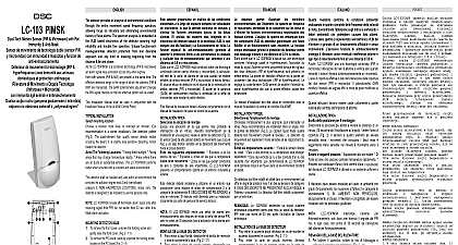
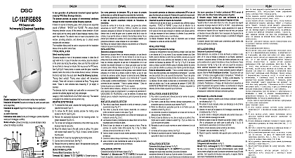
Mono Color PIR Motion Sensor Pet Immunity and Camera option pasivo infrarrojo digital de movimiento inmunidad a mascotas y opci de c de mouvement num IRP des options de cam et immunit aux domestiques di Movimento Digitale ad Infrarossi con agli Animali e Telecamera opzionale czujka ruchu pasywnej podczerwieni PIR na obecno zwierz z opcj kamery 1 Knockout holes I Orificios troquelados I Trous de d I Fori ciechi I Otwory monta 2 Detector Installation I Instalaci del detector I Installation du d I Installazione del rilevatore I Monta czujki High new generation of professional movement spread analyzing detectors with Mono Color Camera sensing device High sensitivity and high resolution board Electronic shutter control sensing device Omnidirectional Installation Manual shall be used in conjunction with the Manual of the ALARM Control Panel INSTALLATION mounting location a location most likely to intercept an intruder Our is a corner installation See detection pattern The quad element high quality sensor detects motion the beam it is slightly less sensitive detecting motion detector The LC 101CAM performs best when with a constant and stable environment the Following Locations Facing direct sunlight Facing that may change temperature rapidly Areas where there air ducts or substantial airflows The LC 101CAM performs when provided with a constant and stable environment detector shall be installed and used within an environment provides the pollution degree max 2 and overvoltages II NON HAZARDOUS LOCATIONS indoor only The is designed to be installed by service persons only DETECTOR BASE To remove the front cover unscrew the holding screw and raise the front cover Fig 2 12 To remove the PC board carefully unscrew the holding screw on the PC board Fig 2 7 Put wire through the bracket and holes Fig 1 Mount the detector base to the wall or on the ceiling with a bracket Fig 5 Use the supplied mounting means and anchors for securing the device to the building Reinstall the PC board by fully tightening the holding screw wire to terminal block Connect the camera cable to connector in PC Replace the cover by inserting it back in the appropriate closing and screw in the holding screw INSTALLATION Block Connections See Fig 5 1 2 Marked TAMPER If a Tamper is required connect these terminals to a 24 hour normally protective zone in the control unit If the front cover of the is opened an immediate alarm signal will be sent to the unit 3 4 Marked OUT GND This is the audio output These two terminals should be connected to an input 4 5 Marked GND OUT This is the video output These two terminals should be connected to video 6,7 8 Marked NO COM NC These are output relay contacts of the detector Connect to a normally or normally opened zone in the control panel 9 Marked GND Connect to the negative Voltage or ground of the control panel 10 Marked Connect to a positive Voltage of 8.2 16VDC source usually from the alarm control unit UP THE DETECTOR ADJUSTMENT Switch 1 2 of DIP 5 Use for Setting provides N O relay Four options Left Position Right RELAY CLOSE OPEN SEC Factory Setting The N C Relay opens for 1.8 2 sec when an alarm SEC SEC que estime m probable Nuestra recomendaci es nueva generaci de detectores pasivos infrarrojos con del espectro ensanchado de de y c mono color de detecci de v C integrada de alta y alta resoluci Control electr del obturador de detecci de audio Respuesta omnidireccional Alta sensibilidad Manual de instalaci deber utilizarse conjuntamente con el de instalaci del panel de control de la alarma T la ubicaci de montaje una ubicaci en de un en una esquina V el patr de detecci Fig 3 sensor Quad de alta calidad detecta el movimiento que cruza el y es algo menos sensible en la detecci del movimiento el propio detector LC 101CAM presenta un comportamiento en un entorno constante y estable las siguientes ubicaciones Expuesto a la luz directa del Expuesto a zonas en las que la temperatura pueda variar Zonas en las que existan conductos de aire o de aire LC 101CAM presenta un en un entorno constante y estable detector deber instalarse y utilizarse en un entorno que como m el grado de contaminaci 2 y la de sobretensi II UBICACIONES NO PELIGROSAS y en interiores El detector est dise para su instalaci por parte de personal de servicio t DE LA BASE DEL DETECTOR Para retirar la tapa frontal desatornille el tornillo de retenci y suavemente la tapa Fig 2 12 Para retirar la placa del circuito impreso desatornille con el tornillo de retenci situado en dicha placa Fig 2 7 Haga pasar el cable a trav del soporte y los orificios A Fig Monte la base del detector en la pared o en el techo con un adecuado Fig 5 Utilice los elementos de montaje tornillos y anclajes para fijar el dispositivo al Vuelva a instalar la placa de circuito impreso apretando a el tornillo de retenci Conecte los cables al bloque de Conecte el cable de la c al conector del circuito impreso Vuelva a colocar la tapa insert de vuelta en las patillas cierre correspondientes y atornille el tornillo de retenci DEL DETECTOR del bloque de terminales v la Fig 5 1 y 2 Marcados como T1 T2 TAMPER Si se una funci de seguridad conecte estos terminales a una protectora normalmente cerrada de 24 horas en la unidad de Si se abre la tapa frontal del detector se enviar una se de alarma a la unidad de control 3 y 4 Marcados como AUDIO OUT GND Se de la salida de la se de audio Estos dos terminales deben a una entrada de audio Terminales 4 y 5 Marcados VIDEO GND OUT Se trata de la salida de la se de Estos dos terminales deben conectarse a una entrada de 6 7 y 8 Marcados como RELAY NO COM y NC trata de los contactos del rel de la salida de alarma del Con a una zona normalmente cerrada o abierta del panel de control 9 Marcado como GND Con a la salida de negativa o a la tierra del panel de control 10 Marcado como 12 V Con a una salida tensi positiva de entre 8,2 y 16 V CC habitualmente de la unidad de control de la alarma DEL DETECTOR DEL TIEMPO Interruptores 1 y 2 del microinterruptor Utilizados para ajustar el tiempo TIME proporcionan un normalmente abierto Cuatro opciones izquierda OFF Posici derecha ON DE CIERRE APERTURA DEL S ajuste de f El rel normalmente cerrado se abre durante entre 1,8 y s cuando se produce una alarma S S nouvelle g