DSC LC103PIMSK IM EN SP FR ITA POL

File Preview
Click below to download for free
Click below to download for free
File Data
| Name | dsc-lc103pimsk-im-en-sp-fr-ita-pol-0185324697.pdf |
|---|---|
| Type | |
| Size | 1.66 MB |
| Downloads |
Text Preview
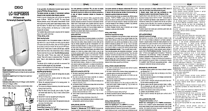
PIMSK Motion Sensor PIR Microwave with Pet Anti Mask de movimiento de tecnolog doble sensor PIR microondas con inmunidad a mascotas y funci de de mouvement bi technologie IRP avec immunit aux animaux et protection antimasque di Movimento a Doppia Tecnologia Microonda immunit agli animali e antimascheramento czujka ruchu pasywna podczerwien i mikrofala na obecnosc zwierzat z 1 Knockout holes I Orificios troquelados I Trous de d I Fori ciechi I Otwory montazowe Installation Wall mount bracket ceiling mount available del soporte Escuadra de montaje en pared escuadra para disponible du support Support de montage mural support pour montage plafond disponible dello snodo Snodo per il montaggio a parete disponibile per il montaggio a soffitto uchwytu Uchwyt do montazu na scianie dostepny takze uchwyt montazu na suficie 2 Detector Installation Instalaci del detector Installation du d Installazione del rilevatore Montaz czujki detector provides an analysis of environmental conditions the entire movement speed frequency spectrum focus on intruders and eliminating environmental of false alarms The spectrum analysis is embedded in VLSI based electronics of the detector assuring high and trouble free operation Unique function anti detector protection from non desirable and any kind of masking beginning from the 0.8m and closer the LC 103PIMSK is a combined technology PIR microwave alarm signal relay activation occurs only when signals both sensors PIR MW are present at the same time The detection range is the range of which the patterns PIR are intersected The GAIN potentiometer adjustment changes MW signal intensity so that the effective pattern will be scaled Installation Manual shall be used in conjunction with the Manual of the ALARM Control Panel INSTALLATION mounting location a location most likely to intercept an intruder Our is a corner installation See detection pattern The quad element high quality sensor detects motion the beam it is slightly less sensitive detecting motion the detector The Following Locations Facing direct sunlight Facing that may change temperature rapidly Areas where there air ducts or substantial airflows The LC 103PIMSK performs when provided with a constant and stable environment detector shall be installed and used within an environment that the pollution degree max 2 and overvoltages II NON HAZARDOUS LOCATIONS indoor only The is designed to be installed by service persons only LC 103PIMSK breaks off Anti Mask alarm signal only after signal from PIR but not earlier then 30 sec after Anti alarm activation DETECTOR BASE To remove the front cover unscrew the holding screw and raise the front cover Fig 2 11 To remove the PC board carefully unscrew the holding screw on the PC board Fig 2 9 Break out the desired holes for proper installation Fig 1 2 or At least 2 screws 3x30mm must be used for mounting to the The circular and rectangular indentations at the bottom base the knockout holes for wire entry Mount the detector base to the wall corner or ceiling For with bracket install bracket Reinstall the PC board by fully tightening the holding screw Connect wire to terminal block Fig 4 Replace the cover by inserting it back in the appropriate pins and screw in the holding screw INSTALLATION Block Connections See Fig 4 1 2 Marked TAMPER Connect these to a 24 hour normally closed protective zone in the unit If the front cover of the detector is opened an alarm signal will be sent to the control unit 3 4 Marked NC C This is the alarm output of Anti Mask detection 5 Marked End of line option Use this terminal connect resistor according to End Of Line configuration terminal provides for the quick installation of a EOL resistor it not connected internally to the detector but instead provides a junction point for the connection of the zone loop wire the control panel to the EOL resistor 6 7 Marked NC C This is the alarm output of PIR detection 8 Marked GND Connect to the negative Voltage or ground of the control panel 9 Marked 12V Connect to a positive Voltage of 8.2 16VDC source UP THE DETECTOR ENABLE DISABLE 1 of DIP 4 Use for Setting Up LED ENABLE The RED LED will activate the detector is in alarm condition Down LED DISABLE The LED are disabled en factores ambientales t de detector proporciona un an de las condiciones a lo largo del espectro completo de velocidades movimiento lo que le permite centrarse en intrusos y falsas El an del espectro est del detector basada en la tecnolog VLSI lo que una alta fiabilidad y un funcionamiento sin fallos La especial de anti enmascaramiento garantiza al la protecci frente a una aproximaci no deseada cualquier tipo de enmascaramiento que comience a una de 0,8 m o m cercana que el LC2 103PIMSK est construido sobe una tecnolog sensor pasivo infrarrojo y microondas la activaci rel de la se de alarma se da s cuando se reciben de ambos sensores PIR y microondas al mismo tiempo alcance eficaz de detecci es el alcance de la intersecci de patrones PIR y microondas El ajuste de la ganancia del potenci modifica la intensidad de la se de para escalar el patr efectivo Manual de instalaci deber utilizarse conjuntamente con el de instalaci del panel de control de la alarma T la ubicaci de montaje una ubicaci en de un en una esquina V el patr de detecci Fig 3 sensor Quad de alta calidad detecta el movimiento que cruza el y es algo menos sensible en la detecci del movimiento el propio detector los siguientes emplazamientos Expuesto a la luz del sol Expuesto a zonas en las que la temperatura variar r Zonas en las que existan conductos aire o corrientes de aire importantes El LC2 103PIMSK un comportamiento en un entorno constante y detector deber instalarse y utilizarse en un entorno que como m el grado de contaminaci 2 y la de sobretensi II UBICACIONES NO PELIGROSAS y en interiores El detector est dise para su instalaci por parte de personal de servicio t El LC2 103PIMSK emite una se de alarma anti s despu de recibir la se del sensor PIR no antes de 30 segundos tras la activaci de la alarma anti DE LA BASE DEL DETECTOR Para retirar la tapa frontal desatornille el tornillo de retenci que estime m probable Nuestra recomendaci es levante suavemente la tapa Fig 2 11 Para retirar la placa del circuito impreso desatornille con el tornillo de retenci situado en dicha placa Fig 2 Taladre los orificios deseados para una instalaci correcta 1 B o C Deber utilizarse al manos dos tornillos de 3 30 mm para el montaje en una pared Las muescas circulares y rectangulares de la base inferior son orificios troquelados para la entrada de cables Monte la base del detector en la pared e