DSC LCD4521(T) - Installation Manual - English - MAXSYS Programmable Fire Message LCD Keypad

File Preview
Click below to download for free
Click below to download for free
File Data
| Name | dsc-lcd4521-t-installation-manual-english-maxsys-programmable-fire-message-lcd-keypad-9432175680.pdf |
|---|---|
| Type | |
| Size | 975.52 KB |
| Downloads |
Text Preview
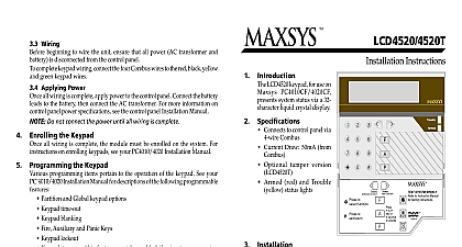
3.3 Wiring beginning to wire the unit ensure that all power AC transformer and is disconnected from the control panel complete keypad wiring connect the four Combus wires red black yellow green to the keypad terminals R B Y G Consult the diagram below Instructions LCD4521 keypad for use on PC4010CF 4020CF system status via a 32 liquid crystal display Connects to control panel via Combus Current Draw 50mA from Optional tamper version Five programmable function Ready green Armed red Trouble yellow status Unpacking LCD4521 package includes the following parts One LCD4521 keypad Four mounting screws One keypad inner door label One set of Fire Auxiliary and Panic key labels Mounting Keypad should be mounted where it is accessible to designated points of entry Once a dry and secure location is selected perform the following steps to the keypad Remove the keypad backplate by loosening the screw located at the base of Secure the keypad backplate to the wall in the desired location Use the screws unit mounting the keypad to its backplate complete keypad wiring refer to the System Installation Manual for information limitations regarding product use and function and on the limitations as to liability of the manufacturer Applying Power all wiring is complete apply power to the control panel Connect the battery to the battery then connect the AC transformer For more information on panel power specifications see the control panel Installation Manual Do not connect the power until all wiring is complete the Keypad all wiring is complete the module must be enrolled on the system For on enrolling keypads see your PC4010 4020 Installation Manual the Keypad programming items pertain to the operation of the keypad See your Installation Manual for descriptions of the following programmable Partition and Global keypad options Keypad time out Keypad blanking Fire Auxiliary and Panic Keys Keypad lockout Keypad tampers this feature must be enabled if using tamper version Function keys the five function keys are programmed as Stay Arm Away Door Chime Activation Reset and Quick Exit by default To alter these from their default settings see the list of available options in the PC4010 v3.0 Installation Manual Function keys are only available when used with PC4010 4020 v3.0 and Products Digital Security Controls Ltd Flint Road Downsview Ontario Canada M3J 2J6 665 8460 Fax 416 665 7498 1 800 387 3630 in Canada 29002889 R0