DSC LINKS2150 v1 4W - Installation Manual - English - Long Range Radio Communicator

File Preview
Click below to download for free
Click below to download for free
File Data
| Name | dsc-links2150-v1-4w-installation-manual-english-long-range-radio-communicator-6723098451.pdf |
|---|---|
| Type | |
| Size | 686.13 KB |
| Downloads |
Text Preview
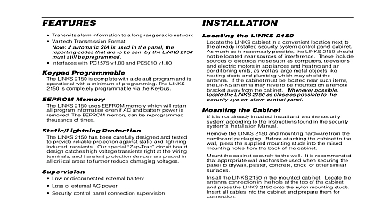
Please refer to the System Installation Manual for information on limitations regarding product use and and information on the limitations as to liability of the manufacturer W A R N I N G Range Radio Transmitter 1.4W of Contents Programmable 1 Memory 1 Protection 1 1 1 1 the LINKS2150 1 the cabinet 1 Terminals 12v 2 Trouble Terminal 2 TRBL Input Terminal 2 TRBL Input Terminal 2 TRBL Output Terminal 2 and PGM PANEL Terminals 2 Terminal 2 and GRN KEYPAD Terminal 2 OUT and V SUP Terminals 2 Connections 2 THE LINKS2150 3 Data 3 Programmed Data 3 Data Programming 3 PROGRAMMING SECTIONS 3 LINKS2150 Programming Sections for PC1575 3 LINKS2150 Programming Section for PC5010 PC1555 PC580 3 2150 Account Code 4 Maintenance Alarm Reporting Codes 4 Maintenance Restoral Reporting Codes 4 Module Configuration 4 Call Direction Options 4 Miscellaneous Alarm Reporting Codes 5 Miscellaneous Restoral Reporting Codes 5 Miscellaneous Alarm Reporting Codes v2.0 panel only 5 Installer Code 96 LINKS2150 Factory Default Programming PC1575 5 Code 993 LINKS2150 Factory Default Programming PC5010 v1.1 or later PC5015 PC1555 PC580 5 THE RECORD PROGRAMMING WORKSHEETS LINKS2150 Programming Sections PC1575 7 LINKS2150 Programming Section PC5010 PC5015 PC1555 PC580 7 RF Identification Code 7 Maintenance Alarm Reporting Codes 7 Maintenance Restoral Reporting Codes 7 Module Configuration8 7 Call Direction Options 7 Miscellaneous Alarm Reporting Codes 8 Miscellaneous Restoral Reporting Codes 8 Miscellaneous Alarm Reporting Codes v2.0 panel only 8 Restore LINKS2150 Factory Default for PC1575 8 Restore LINKS2150 Factory Default for PC5010 v1.1 or later Pc5015 PC580 8 DIAGRAM WARRANTY BACK PAGE manual is for the LINKS2150 software version 1.4W Transmits alarm information to a long range radio network Varitech Transmission Format If automatic SIA is used in the panel the codes that are to be sent by the LINKS2150 still be programmed May be used with the following DSC alarm control PC5010 v1.0 and up PC5015 v2.2 and up PC1575 v1.0 PC1555 v2 x and up PC580 v2 x and up via Keypad or Software LINKS2150 is complete with a default program and will with a minimum of programming You can program the at any system keypad or using DLS 1 v6.7 or Memory LINKS2150 uses EEPROM memory which will retain all information even if AC and battery power is removed EEPROM memory can be reprogrammed thousands of Protection LINKS2150 has been carefully designed and tested to reliable protection against static and lightning induced Our special circuit board design catches voltage transients right at the wiring terminals and protection devices are placed in all critical areas to reduce damaging voltages Low or disconnected external battery Loss of external AC power Security control panel connection supervision Long range radio alarm transmitter 4 LINKS2150 Trouble Reporting Codes and Test Reporting Code 2 negative triggered trouble inputs negative voltage trigger 0 to 0.8 VDC Required power supply 11.5 to 14VDC at 1A separate power supply must be used Do not power LINKS2150 from the keybus Radio transmitter frequency as specified on transmitter Trouble Output 50mA Antenna not supplied Larsen MHW 450 50 W 450 470 MHz LINKS2150 cabinet dimensions 11 high 11.8 wide 3.3 mm 300 mm 84mm Cabinet colour light beige vertical antenna the LINKS2150 the LINKS cabinet in a convenient location next to the installed security system control panel cabinet As as is reasonably possible do not mount the LINKS2150 sources of interference These include sources of noise such as computers televisions and electric in appliances and heating and air conditioning units well as large metal objects like heating ducts and plumbing may shield the antenna If the cabinet must be located such items the LINKS antenna may have to be mounted a remote bracket away from the cabinet Whenever mount the LINKS2150 as close as possible to the system alarm control panel the Cabinet it is not already installed install and test the security system to the instructions found in the security system Manual the LINKS2150 and mounting hardware from the packaging Before attaching the cabinet to the press the supplied mounting studs into the raised mounting from the back of the cabinet the cabinet securely to the wall It is recommended that wall anchors be used when securing the panel to plaster concrete brick or other similar surfaces the LINKS2150 in the mounted cabinet Locate the connection in the hole at the top of the cabinet and the LINKS2150 onto the nylon mounting studs Insert cables into the cabinet and prepare them for connection the antenna to the LINKS2150 antenna connector the antenna tight only An antenna should always be connected to the whenever it is operated The unit will not properly and may be damaged if an antenna is installed not connect the power supply until all other wiring the antenna connection has been completed checked to ensure that it is correct Incorrect connections may cause the LINKS unit to improperly or may damage the LINKS unit DO NOT connect both a and a LINKS2150 to the same system can connect both a PC5400 module and a LINKS2150 to same system Terminals 12v Do not apply power to the unit until all wiring con are completed and the antenna is attached to the the power terminals 12V to the BELL and terminals or to a separate 11.5 14Vdc 1A power If you will be using a local bell or siren use a power supply for the LINKS2150 Do not the LINKS2150 to the Keybus RED terminal The current drawn by the LINKS2450 and the siren s to the Bell terminals must not exceed that speci by the rating of the control panel Refer to your control Intallation Manual for more information wiring between the


