DSC NT9005DMK - Installation Manual - English - French - Spanish - Envoy LCD Desk Mount Kit

File Preview
Click below to download for free
Click below to download for free
File Data
| Name | dsc-nt9005dmk-installation-manual-english-french-spanish-envoy-lcd-desk-mount-kit-2850631497.pdf |
|---|---|
| Type | |
| Size | 668.66 KB |
| Downloads |
Text Preview
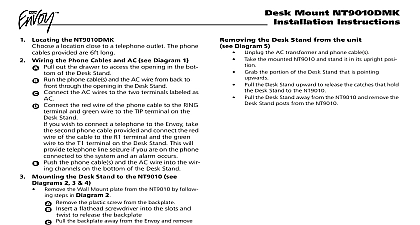
1 Locating the NT9005DMK a location close to a telephone outlet The phone cables are 6ft long Connecting the Deskstand to the NT9005 Backplate the backplate from the NT9005 see the NT9005 for further instructions Connect the desk stand to NT9005 backplate as shown in Diagram 1 and 2 out the desk stand drawer to access the opening in the of the desk stand see Diagram 1 the phone cable s and the AC wire from back to front the opening in the desk stand to the NT9005 ter block the AC wires see Diagram 3 the red wire of the phone cable to the RG terminal green wire to the TP terminal the terminal block you wish to connect a telephone to the Envoy LCD take second phone cable provided and connect the red wire the cable to the R1 terminal and the green wire to the T1 on the Envoy LCD This will provide telephone line if you are on the phone connected to the system an alarm occurs the phone cable s and the AC wire into the wiring on the bottom of the desk stand to the two terminals labeled as Additional Wiring additional wiring that connects to the terminal block on the backplate must be run through the Desk Stand and in the wiring channels on the bottom of the Desk Mounting the Desk Stand to the NT9005 the Desk Stand is mounted on the NT9005 backplate and wiring is complete connect the backplate to the NT9005 see NT9005 manual for further instructions Once this is com and the unit is in its desired location plug the phone connected to TP and RG into the wall outlet and connect other phone cable to the telephone if applicable that the unit is set up apply AC power set up devices and all programming as described in the NT9005 manuals Removing the Desk Stand from the Unit Diagram 4 the AC transformer and phone cable s the back plate from the NT9005 all wiring from the terminal block on the back plate the NT9005 back plate and stand it in its upright posi the portion of the Desk Stand that is pointing Pull the Desk Stand upward and outward simulta to release the catches that hold the Desk Stand to NT9005 back plate the Desk Stand down to release the catches that hold to the NT9005 back plate Mount NT9005DMK Instructions Warranty Security Controls Ltd warrants that for a period of 12 months from the date purchase the product shall be free of defects in materials and workmanship normal use and that in fulfilment of any breach of such warranty Digital Controls Ltd shall at its option repair or replace the defective equipment return of the equipment to its repair depot This warranty applies only to in parts and workmanship and not to damage incurred in shipping or han or damage due to causes beyond the control of Digital Security Controls Ltd as lightning excessive voltage mechanical shock water damage or damage out of abuse alteration or improper application of the equipment foregoing warranty shall apply only to the original purchaser and is and shall in lieu of any and all other warranties whether expressed or implied and of all obligations or liabilities on the part of Digital Security Controls Ltd Digital Controls Ltd neither assumes responsibility for nor authorizes any other purporting to act on its behalf to modify or to change this warranty nor to for it any other warranty or liability concerning this product no event shall Digital Security Controls Ltd be liable for any direct indirect or damages loss of anticipated profits loss of time or any other losses by the purchaser in connection with the purchase installation or opera or failure of this product Digital Security Controls Ltd recommends that the entire system be tested on a regular basis However despite frequent testing and due but not limited to criminal tampering or electrical disruption it is possible this product to fail to perform as expected Information Changes or modifications not expressly approved by Security Controls Ltd could void the user authority to operate this de Table NT9005DMK d limit Security Controls Lt pendant une p de douze mois partir de la date d le produit contre toute d mat et d dans des conditions d Dans l de cette garantie Digital Security Controls Lt va le juge opportun en cas de probl de fonctionnement r ou remplacer les d d leur retour son d de r Cette garantie s aux d et la main d et non aux dommages caus lors l ou de la manipulation ni aux dommages dont les causes d le contr Digital Security Controls Lt telles que la foudre les surtensions les chocs m d d ou tout dommage provenant d de modifications ou de mauvaises utilisa de l garantie susdite n valide que pour l original et n et ne sera que la seule des valables qu ait exprim ou implicite rempla toute autre obligation ou de la part de Digital Security Controls Lt La pr garantie contient la au complet Digital Security Controls Lt n aucune autre personne agir son nom pour modifier ou changer la pr garantie et n assume pas la responsabilit a assumer en son nom toute autre garantie ou responsabilit concernant le pr produit aucun cas Digital Security Controls Lt ne pourra tenue responsable des con directes ou indirectes de dommages relativement la perte de profits pr la de temps ou toute autre perte subie par l en rapport avec l l le fonctionnement ou la d du pr produit Digital Security Controls Lt recommande que le syst soit soumis un essai complet Cependant en d d r et cause criminelles pannes de courant ou autres il est possible que le fonctionne du produit ne soit pas conforme aux sp IMPORTANTE Tout changement ou modification qui n pas approuv par Digital Security Controls Ltd pourrait annuler le droit d cet Emplacement NT9005DMK un emplacement pr d prise de t Le t est fourni avec des c t de 1,8 m 6 de longueur Fixation du support de table la plaque de montage NT9005 la plaque de montage du NT9005 pour de plus renseignements voir le manuel du NT9005 Con le support de table la plaque de montage du comme illustr par les diagrammes 1 et 2 le tiroir du support de table afin d au trou au fond du support voir diagramme 1 passer le s fil s t par le trou du sup de l vers l et au bloc de branchement du les fils de courant alternatif c a voir diagramme 3 le fil rouge du c t la borne RG le fil vert la borne TP sur le bloc de branchement vous d brancher un t Envoy LCD prenez deuxi c t fournis et branchez le fil du c la borne R1 et le fil vert la borne T1 sur LCD Cela permettra de saisir la ligne si vous au branch sur le syst lorsqu alarme est le s c t et le fil dans conduites situ sous le support de table aux deux bornes C suppl c suppl connect au bloc de branchement la plaque de