DSC PC4020 v3 0 - Standby Battery Calculation Chart - English

File Preview
Click below to download for free
Click below to download for free
File Data
| Name | dsc-pc4020-v3-0-standby-battery-calculation-chart-english-6498127350.pdf |
|---|---|
| Type | |
| Size | 660.58 KB |
| Downloads |
Text Preview
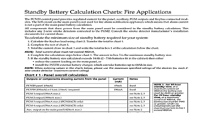
PC4010CF 4020CF v3.0 Standby Battery Calculation Charts Battery Calculation Chart Applications PC4010CF 4020CF control panel provides regulated current for the panel Auxiliary switched Auxiliary PGM outputs loop devices and Combus connected modules The bell circuit on the main panel is not used for fire alarm noti appliances which means that alarm current is not a part of the main panel battery calculation Fire Alarm Notifica appliances are powered by one or more PC4702BP panels connected to the Combus Each of the PC4702BP panels has its standby battery See Figure 1 Typical System Layout components that draw power from the main panel must be considered in the standby battery calculation This includes 2 wire smoke detectors connected to the PC4701 2 wire smoke zone Consult the smoke detector manufacturer instal documents for current draw calculate the minimum size of standby battery required for your system If you are using addressable devices calculate the current load on each of the addressable loops using charts 2 and 3 chart 2 is required for the PC4010CF Tranfer the totals to chart 1 Calculate the Combus load using chart 4 Transfer the total to chart 1 Complete the rest of chart 1 Total the current draw in chart 1 and write the total in box 1 of the calculation below the chart Complete the calculation steps below chart 1 The answer in box 5 is the minimum standby battery size If the standby battery size calculated exceeds 14 Ah 2 7Ah batteries fit in the cabinet then either reduce the current loading on the main panel or install the PS4350 external battery charger which can take batteries up to 60Ah in size easiest way to reduce current loading is to use a PC4204CF configured for Combus repower to power all the system that are connected to the Combus see Figure 1 See chart 5 for PC4204CF standby battery calculation 1 Panel overall calculation or components drawing current from panel panel 97mA OR PC4020 130mA panel fire module mounted in the main cabinet 1 only Communicator Max detectors connected to the PC4701 fire module 1 output 50 mA max 2 output 50 mA max PC4020CF panels only loop 1 170 mA max loop 2 170 mA max PC4020CF panels only output on the main panel 500 mA max output on the main panel 300 mA max load 500 mA max Note 2 Note 2 Chart 2 Chart 3 Note 3 Note 3 Chart 4 1 60 hours time the battery is and the current exceed 24 hours time largest battery 31Ah and the current exceed no can maximum in line 1 1065mA current from the main control panel See Note 1 1 time 24 or 60 hours 2 total standby current in mA 1 the standby time in hours 2 Write total in box 3 1 x 2 3 factor conversion to Amp Hours 4 3 by the derating factor 4 3 x 4 5 Amp Hour is the minimum size battery required to maintain the main panel for the standby time selected Alarm notification power is not supplied by the PC4010CF 4020CF panel and is therefore not part of this calcu See the PC4702BP description on the last page 2 PGM1 and PGM2 can used as standard PGM out or as addressable loops output configured as a output can supply up to maximum Each output as an addressable can supply up to 170mA 3 The total current for the AUX output the SAUX output is 500mA of the 500mA can be drawn the AUX output and in case none can be taken the SAUX output maximum current that can drawn from the SAUX out is 300mA and in this case 200mA would remain for AUX output add up the current for components that are the control panel and first PC4204CF module components on the Combus are connected after the PC4204CF should be pow from the PC4204CF and not draw current from main control panel Chart 5 for PC4204CF battery calculation 1 Typical System Layout 2 Addressable Loop 1 Loading for chart 2 current addressable loop 1 to Chart 1 3 Addressable Loop 2 Loading PC4020CF only for chart 3 current addressable loop 2 to Chart 1 4 Combus Loading series series output current of PC4108A output current of PC4116 for connected devices for chart 4 current on the Combus to Chart 1 Chart for PC4204CF Quad Relay and Combus Repower Module PC4204CF in the system must be evaluated for standby loading If the first PC4204CF is loaded beyond capacity or the batteries within its cabinet cannot support the required standby time then another panel must be added The standby time for each PC4204CF in the system is calculated indepen Each PC4204CF panel can accommodate up 14 Ah worth of batteries 2 7Ah batteries If more than one PC4204CF is used in the system copy this page and repeat the calculation for PC4204CF panel used calculate the minimum size of standby battery required for the PC4204CF Complete chart 5 Total the current draw in chart 5 and write it in box 1 of the calculation below the chart Complete the calculation steps below chart 5 The answer in box 5 is the PC4204CF minimum standby 2 Typical PC4204CF Layout size 5 Standby calculation for PC4204CF series series output current of PC4108A output current of PC4116 for connected devices drawn from the Aux output current supplied by PC4204CF see Note 4 1 time 24 or 60 hours 2 total current in mA 1 the standby time in hours 2 1 x 2 3 5 If the PC4204CF is not set up Combus repower include the cur drawn by the downstream com battery for either the previous or the main panel the PC4204CF is set up for Combus include the current drawn by downstream components in the calculation for this module current drawn from the AUX out must be included in the standby for this PC4204CF module 4 With a battery and hours standby the maximum supplied is hours standby the maximum supplied is factor conversion to Amp Hours 4 3 by the derating factor 4 3 x 4 5 is the minimum size battery required to maintain the PC4204CF for the time selected Alarm Notification Standby PC4702BP panel in the system requires 2 4Ah batteries in series to provide standby power This capac is sufficient for at least 60 hours of standby because when AC is lost the Combus provides supervisory for the dual bell module Nothing is drawn from the batteries in standby mode Digital Security Controls Ltd Canada www dsc com Support 1 800 387 3630 in Canada 29003350 R005 all comments concerning this to pubs dscltd com