DSC PC4204CF v3 0 - Installation Manual - English - MAXSYS Power Supply Relay Output Commercial Fire Module

File Preview
Click below to download for free
Click below to download for free
File Data
| Name | dsc-pc4204cf-v3-0-installation-manual-english-maxsys-power-supply-relay-output-commercial-fire-module-5641289307.pdf |
|---|---|
| Type | |
| Size | 706.46 KB |
| Downloads |
Text Preview
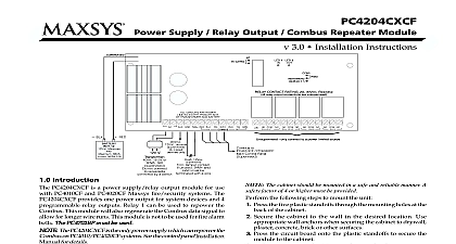
Power Supply Relay Output Combus Repeater Module 3.0 Installation Instructions Introduction PC4204CX is a Power Supply Relay Output Combus Repeater The PC4204CX provides a power output for system devices programmable relay outputs and an output to regenerate the data signal to allow for longer wire runs Do not use any power supply other than the PC4204CX to repower Combus If a power supply other than the PC4204CX is used the repower function will not operate as intended See the control Installation Manual for details regarding this feature Specifications Transformer 16VAC 40VA to 80VA may be used to power the Backup battery 4Ah to 38Ah not provided Connects to control panel via 4 wire Combus Current draw from Combus 30mA Four programmable relay contacts rated 2A 30VDC Selectable battery charging current 800mA or 1.2A AUX current 2.2A max with 800mA battery charge current 80VA transformer Tamper connection Installing the PC4204CX PC4204CX should be located inside a compatible cabinet in a dry secure location The PC4204CX must be installed within a fire enclosure as in EN60950 The cabinet must comply with the battery installation instructions The cabinet should be mounted in a safe and reliable manner A factor of 4 or higher must be provided the following steps to mount the unit Press the five plastic standoffs through the mounting holes the back of the cabinet Secure the cabinet to the wall in the desired location Use wall anchors when securing the cabinet to plaster concrete brick or other surfaces Press the circuit board onto the plastic standoffs to secure module to the cabinet the unit is mounted wiring may be completed Installation and Wiring The PC4204CX is intended to be PERMANENTLY CONNECTED should be installed by service personnel only beginning to wire the unit ensure that all power AC and battery is disconnected from the control panel the following steps to complete wiring Connect the four panel originating Combus wires to the Connect the red black yellow and green wires to the RED BLK YEL and GRN Combus In respectively Relay 1 is being used for Combus power connect the wires according to the diagram below Note that this option jumper Con3 must also be set for 1 refer to the System Installation Manual for information on limitations regarding product use function and information on the limitations as to liability of the manufacturer modules repowered by the PC4204CX should the black yellow and green Combus wires connected the BLK YEL and GRN Combus Out terminals Complete all output wiring Connect the external tamper switch if used the wiring diagrams for further information Current Calculation Chart mA mA required for connected devices required for connected devices required for connected devices Combus Curr Combus Curr Combus Curr Combus Current Combus Curr These modules draw current from the Combus to power devices to the module This current must be added to the total Combus See manufacturer specifications for the current draw of each Each LED assembly draws up to 20mA of current Operation and Wiring Combus is used by the control panel and the modules to with each other When the PC4204CX is used to repower extend the Combus please refer to the wiring diagram for the wiring procedure NOTE Please follow the diagram exactly can be home run connected in a daisy chain or T tapped on the Combus following rules MUST be followed when wiring the Combus The Combus must be run in minimum 22 gauge wire No module can be more than 1000 305m in cable length from PC4204CX Shielded wire should only be used in areas that present excessive noise or electromagnetic interference If shielded wire is used maximum distance a module can be located from the is significantly reduced Check the capacitance rating the wire to calculate the maximum distance see NOTE Shielded wire is not recommended The total capacitance of the Combus wiring must not exceed 80nF the control panel and PC4204CX module or between two modules see Limits below Ratings order for the system to operate properly the power output of the module cannot be exceeded The maximum available AUX current is dependent on the size of the transformer used as as the selected battery charge current Use the following chart determine the maximum AUX supply current Supply Curr Supply Curr Supply Currententententent AUX Supply Curr Supply Curr Comm C C C C CHARGE 800mA 1.2A When using the PC4204CX to repower additional Combus modules calculations must be made to ensure that the maximum AUX supply is not exceeded Ratings current draw of compatible modules is listed below Draw mA Draw mA Draw mA Draw mA Draw mA LCD45XX 50 Zone Expander 30 Zone Expander 30 Wireless Receiver 110 Fire Module 35 Dual Bell Output Module 75 Relay Output Module 30 Low Current Output Module 15 Audio Assistant 150 Printer Module 30 Access Control Module 35 Audio Interface Module 65 Serial Interface Module 35 Telephone Entry Module 135 Total Current Requirement you have determined which modules will draw power from the panel use the following chart to calculate the Combus current Distance Combus Extensions length of Combus from a PC4204CX Combus Regenerator can extended beyond 1000ft 305m providing the following are met Combus must be regenerated and repowered at both ends of wire run using the PC4204CX No other modules are to be connected along the long distance run A maximum distance of 4000ft 1220m can be achieved between PC4204CX devices To extend further additional PC4204CX should be used The wiring used to connect this equipment must be insulated with TFE PTFE FEP neoprene or polymide extending Combus long distances use the following chart to what gauge of wire is necessary Length 600m 900m 1200m Loss current is drawn through a piece of wire voltage will be lost to the wire resistance This voltage loss must be considered all installations ensure proper operation at least 12.5VDC must be applied to all on the system when AC is applied and the battery is fully If less than 12.5VDC is applied system operation will be affected correct the problem try any or all of the following Connect another PC4204CX power supply near the module to power to the Combus Reduce the length of the Combus run to the module Increase the gauge of wire Limits increase in capacitance on the Combus will affect data and will cause the system to slow down Capacitance