DSC PC5100 v1 0 IM EN NA

File Preview
Click below to download for free
Click below to download for free
File Data
| Name | dsc-pc5100-v1-0-im-en-na-0476519832.pdf |
|---|---|
| Type | |
| Size | 723.24 KB |
| Downloads |
Text Preview
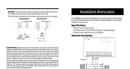
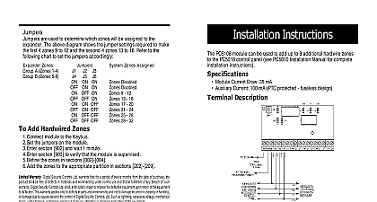
Installation E C U R I T Y S Y S T E M refer to the System Installation Manual for information limitations regarding product use and function and informa on the limitations as to liability of the manufacturer 1 O COMPLIANCE STATEMENT Changes or modifications not expressly approved by Digital Security Controls Ltd could void your to use this equipment equipment has been tested and found to comply with the limits for a Class B digital device pursuant to Part of the FCC Rules These limits are designed to provide reasonable protection against harmful interference in a installation This equipment generates uses and can radiate radio frequency energy and if not installed used in accordance with the instructions may cause harmful interference to radio communications However is no guarantee that interference will not occur in a particular installation If this equipment does cause harmful to radio or television reception which can be determined by turning the equipment off and on the user encouraged to try to correct the interference by one or more of the following measures the receiving antenna the separation between the equipment and receiver the equipment into an outlet on a circuit different from that to which the receiver is connected the dealer or an experienced radio television technician for help user may find the following booklet prepared by the FCC useful to Identify and Resolve Radio Interference Problems This booklet is available from the U S Government Printing Office Washing D C 20402 Stock 004 000 00345 4 Security Controls Ltd 160 Washburn St Lockport NY 14094 Class B digital apparatus complies with Canadian ICES 003 appareil num de la classe B est conforme la norme NMB 003 du Canada Warranty Security Controls Ltd warrants that for a period of twelve months from the date of purchase the shall be free of defects in materials and workmanship under normal use and that in fulfilment of breach of such warranty Digital Security Controls Ltd shall at its option repair or replace the equipment upon return of the equipment to its factory This warranty applies only to defects in and workmanship and not to damage incurred in shipping or handling or damage due to causes the control of Digital Security Controls Ltd such as lightning excessive voltage mechanical water damage or damage arising out of abuse alteration or improper application of the equip foregoing warranty shall apply only to the original buyer and is and shall be in lieu of any and all warranties whether expressed or implied and of all other obligations or liabilities on the part of Security Controls Ltd This warranty contains the entire warranty Digital Security Controls Ltd assumes nor authorizes any other person purporting to act on its behalf to modify or to change warranty nor to assume for it any other warranty or liability concerning this product no event shall Digital Security Controls Ltd be liable for any direct or indirect or consequential loss of anticipated profits loss of time or any other losses incurred by the buyer in connection the purchase installation or operation or failure of this product Digital Security Controls Ltd recommends that the entire system be completely tested on regular basis However despite frequent testing and due to but not limited to criminal tampering or disruption it is possible for this product to fail to perform as expected Specifications 2 Wire Addressable Device Interface Module The PC5100 is an interface module for the PC5010 and PC5015 control panels The module is used to connect 2 wire devices to the Power832 Security System Current draw 40mA Addressable loop maximum current draw 170mA Up to 32 2 wire addressable devices can be added to the system Compatiblilty PC5010 v2 x or higher PC5015 v2 x or higher Multiplex Loop AML Devices addressable series devices use a 2 wire connection for power and communicate with the control panel This simplifies wiring and fast and efficient installations Connect only DSC Addressable Series devices to the loop connections Connection of ANY other type of will impair operation Any devices other than Addressable devices which require power to operate must be powered cid 2 cid 2 cid 3 cid 4 cid 5 cid 5 cid 6 cid 7 cid 8 cid 4 cid 9 cid 10 cid 4 cid 11 cid 12 cid 13 cid 4 cid 9 cid 14 cid 15 cid 3 cid 3 cid 4 cid 16 cid 17 cid 9 cid 18 cid 19 cid 6 cid 2 cid 12 cid 16 cid 20 evice escription Detector mA mA mA Detector mA mA mA Mount Motion mA mA mA Immune Motion Detector mA mA mA Detector mA mA mA mA mA mA Point Module use the Standby Current Draw when calculating maximum wire run lengths to continuous technological changes and product enhance the above table is intended only as a guide Always verify current draw of each device by consulting the Installation provided with the product at the time of purchase Started Connecting the PC5100 Interface Module all power from the control panel before connecting module to the system the PC5100 to the PC5010 5015 Keybus by inserting the red yellow and green Keybus wires into their corresponding termi the PC5100 is not located within the main cabinet a PC5204 supply must be used to power the module as in the below wiring is complete add power back to the PC5010 PC5015 system will detect the new module and it will be supervised Calculating Current Draw to 32 addressable devices can be connected to the PC5100 a maximum of 170mA of current can be used on the address loop Calculate how much current your selection of devices will by completing the following table x Device Draw in standby mode Smoke Detector PIR Detector Ceiling Mount PIR Dual PIR Detector Glass break Detector Magnetic Door Window Contact Contact Input Module Fire Point Module mA mA mA mA mA mA mA Current Draw Maximu m 170 mA Connecting 2 Wire AML Devices 2 wire addressable devices are connected to the STR and STR on the PC5100 All devices can be home run t tapped or in a daisy chain Please refer to the diagram below wiring length of each addressable loop is restricted to the following depending on the amount of current required see Section Current Draw Consult the wiring chart on the next longer wire runs you can split addressable devices onto two more loops from the STR termi For example 32 AMB 300 2.5mA each take 80mA In one 18AWG wire run this allow a maximum length of feet 220 m If you split the 32 into two wire runs of 16 each using 18AWG wire wire run could be 1736 feet m long See the diagram on right more than four conductors be connected to a terminal as wire may cause improper devices must be enrolled as zones on the system entering their serial numbers section 3.2 Current vs Wiring Distance loop mA AWG AWG ft m ft m any of the system keypads indicate a PC5100 module tamper if any zones show as open or show a zone fault there may a short on the AML loop The PC5100 module and zones will be restored until the short is corrected remove power th