DSC PC5108RD v3 0 IS ENG INT

File Preview
Click below to download for free
Click below to download for free
File Data
| Name | dsc-pc5108rd-v3-0-is-eng-int-4523967108.pdf |
|---|---|
| Type | |
| Size | 728.36 KB |
| Downloads |
Text Preview
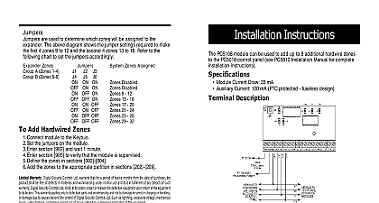
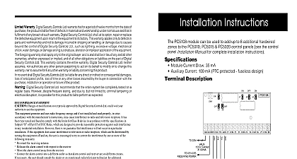
Terminal Connections This can be used to provide tamper protection for the cabinet where the PC5108RD is Connect a normally closed NC switch across TAM and BLK If the tamper is not used connect a piece of wire across TAM and BLK to remove the trouble condition Used to provide power for devices The maximum current draw must not 100mA Connect the positive lead of powered devices to VAUX and the nega to BLK or any COM terminal The 4 wire KEYBUS connection is used by the panel to communicate with module Connect the RED BLK YEL and GRN terminals to the KEYBUS terminals the PC5009 Z8 Wire the zones according to the description found in the control panel Installa Manual WARRANTY Security Controls Ltd warrants that for a period of twelve months from the date of purchase the product shall free of defects in material and workmanship under normal use and that in fulfilment of any breach of such war Digital Security Controls Ltd shall at its option repair or replace the defective equipment upon return of the to its repair depot This warranty applies only to defects in parts and workmanship and not to damage in shipping or handling or damage due to causes beyond control of Digital Security Controls Ltd such as excessive voltage mechanical shock water damage or damage arising out of abuse alteration or improper of the equipment The foregoing warranty shall apply only to the original buyer and is and shall be in of any and all other warranties whether express or implied and of all other obligations or liabilities on the part of Security Controls Ltd This warranty contains the entire warranty Digital Security Controls Ltd neither responsibility nor authorizes any other person purporting to act on its behalf to modify or to change this nor to assume for it any other warranty or liability concerning this product In no event shall Digital Secu Controls Ltd be liable for any direct indirect or consequential damages loss of anticipated profits loss of time any other losses incurred by the buyer in connection with the purchase installation or operation or failure of this DSC Ltd recommends that the entire system be completely tested on a regular basis However despite testing and due to but not limited to criminal tampering or electrical disruption it is possible for this to fail to perform as expected Installation Instructions PC5108RD module can be used to add up to 8 additional hardwired zones to the control panel see the control panel Installation Manual for complete installation Module Current Draw 35 mA Auxiliary Current 100 mA PTC protected fuseless design Connections PC5108RD terminal strip provides connection to the PC5009 control panel and devices Refer to figure 1 and the PC5009 Installation Manual for more details Add Hardwired Zones to a Control Panel Connect module to the Keybus with the panel powered down Power up the system Enter section 902 and wait 1 minute Enter section 903 to verify that the module is supervised Define the zones in section 002 1 COM Devices Power 100mA to preceding module or panel to additional modules Digital Security Controls Ltd Canada cid 127 www dsc com Support 1 800 387 3630 Canada US or 905 760 3036 in Canada Rev 002 all comments concerning this publication to pubs dscltd com Zone Expander 3 O Connections This can be used to provide tamper protection for the cabinet where the PC5108RD is Connect a normally closed NC switch across TAM and BLK If the tamper is not used connect a piece of wire across TAM and BLK to remove the trouble condition Used to provide power for devices The maximum current draw must not 100mA Connect the positive lead of powered devices to VAUX and the nega to BLK or any COM terminal The 4 wire KEYBUS connection is used by the panel to communicate with module Connect the RED BLK YEL and GRN terminals to the KEYBUS terminals the PC5009 Z8 Wire the zones according to the description found in the control panel Installa Manual WARRANTY Security Controls Ltd warrants that for a period of twelve months from the date of purchase the product shall free of defects in material and workmanship under normal use and that in fulfilment of any breach of such war Digital Security Controls Ltd shall at its option repair or replace the defective equipment upon return of the to its repair depot This warranty applies only to defects in parts and workmanship and not to damage in shipping or handling or damage due to causes beyond control of Digital Security Controls Ltd such as excessive voltage mechanical shock water damage or damage arising out of abuse alteration or improper of the equipment The foregoing warranty shall apply only to the original buyer and is and shall be in of any and all other warranties whether express or implied and of all other obligations or liabilities on the part of Security Controls Ltd This warranty contains the entire warranty Digital Security Controls Ltd neither responsibility nor authorizes any other person purporting to act on its behalf to modify or to change this nor to assume for it any other warranty or liability concerning this product In no event shall Digital Secu Controls Ltd be liable for any direct indirect or consequential damages loss of anticipated profits loss of time any other losses incurred by the buyer in connection with the purchase installation or operation or failure of this DSC Ltd recommends that the entire system be completely tested on a regular basis However despite testing and due to but not limited to criminal tampering or electrical disruption it is possible for this to fail to perform as expected Installation Instructions PC5108RD module can be used to add up to 8 additional hardwired zones to the control panel see the control panel Installation Manual for complete installation Module Current Draw 35 mA Auxiliary Current 100 mA PTC protected fuseless design Connections PC5108RD terminal strip provides connection to the PC5009 control panel and devices Refer to figure 1 and the PC5009 Installation Manual for more details Add Hardwired Zones to a Control Panel Connect module to the Keybus with the panel powered down Power up the system Enter section 902 and wait 1 minute Enter section 903 to verify that the module is supervised Define the zones in section 002 1 COM Devices Power 100mA to preceding module or panel to additional modules Digital Security Controls Ltd Canada cid 127 www dsc com Support 1 800 387 3630 Canada US or 905 760 3036 in Canada Rev 002 all comments concerning this publication to pubs dscltd com Zone Expander 3 O