DSC PC5204 v2 0 - Installation Manual - English - PowerSeries Power Supply Module

File Preview
Click below to download for free
Click below to download for free
File Data
| Name | dsc-pc5204-v2-0-installation-manual-english-powerseries-power-supply-module-4516892073.pdf |
|---|---|
| Type | |
| Size | 926.68 KB |
| Downloads |
Text Preview
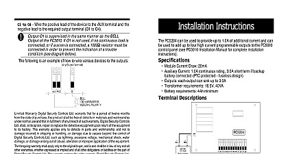
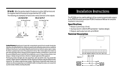
O1 to O4 Wire the positive lead of the device to the AUX terminal and the lead to the required output terminal O1 to O4 O1 is supervised in the same manner as the BELL Output of PC50X0 If O1 is not used if no continuous load is connected or if siren is connected a 1000 resistor DSC model EOLR 1 must be in order to prevent the indication of a trouble condition diagram below following is an example of how to wire various devices to the outputs The PC5204 is not suitable for fire alarm annunciation The PC5204 is not suitable for fire alarm annunciation The PC5204 is not suitable for fire alarm annunciation The PC5204 is not suitable for fire alarm annunciation The PC5204 is not suitable for fire alarm annunciation output RED Siren maximum polarity Warranty Security Controls Ltd warrants that for a period of twelve months from the date of purchase the product shall free of defects in materials and workmanship under normal use and that in fulfilment of any breach of such Digital Security Controls Ltd shall at its option repair or replace the defective equipment upon return of the to its factory This warranty applies only to defects in parts and workmanship and not to damage incurred in or handling or damage due to causes beyond the control of Digital Security Controls Ltd such as lightning voltage mechanical shock water damage or damage arising out of abuse alteration or improper of the equipment foregoing warranty shall apply only to the original buyer and is and shall be in lieu of any and all other warranties whether or implied and of all other obligations or liabilities on the part of Digital Security Controls Ltd This warranty contains entire warranty Digital Security Controls Ltd neither assumes responsibility for nor authorizes any other person to act on its behalf to modify or to change this warranty nor to assume for it any other warranty or liability concerning product no event shall Digital Security Controls Ltd be liable for any direct or indirect or consequential damages loss of profits loss of time or any other losses incurred by the buyer in connection with the purchase installation or or failure of this product Digital Security Controls Ltd recommends that the entire system be completely tested on a regular basis despite frequent testing and due to but not limited to criminal tampering or electrical disruption it is possible this product to fail to perform as expected COMPLIANCE STATEMENT Changes or modifications not expressly approved by Digital Security Controls Ltd could void your authority to use this equipment equipment generates and uses radio frequency energy and if not installed and used properly in strict accordance with the manufacturer may cause interference to radio and television reception It has been type tested and found to comply with the limits for Class B in accordance with the specifications in Subpart of Part 15 of FCC Rules which are designed to provide reasonable protection such interference in any residential installation However there is no guarantee that interference will not occur in a particular If this equipment does cause interference to television or radio reception which can be determined by turning the equipment off on the user is encouraged to try to correct the interference by one or more of the following measures Re orient the receiving antenna Relocate the alarm control with respect to the receiver Move the alarm control away from the receiver Connect the alarm control into a different outlet so that alarm control and receiver are on different circuits necessary the user should consult the dealer or an experienced radio television technician for additional suggestions The user may find the booklet prepared by the FCC useful to Identify and Resolve Radio Television Interference Problems This booklet is available from U S Government Printing Office Washington D C 20402 Stock 004 000 00345 4 2004 Digital Security Controls Ltd Canada www dsc com Support 1 800 387 3630 in Canada Instructions PC5204 can be used to provide up to 1.0A of additional current and can be to add up to four high current programmable outputs to the PC50X0 control see PC50X0 Installation Manual for complete installation instructions Table 1 eriF eriF eriF eriF eriF eriF eriF eriF be used with the PC5020CF only Panels PC5010 PC5015 PC5020 Descriptions Supervised the PC5204 requires a 16.5V 37VA or 16V 40VA transformer Connect primary of the transformer to an unswitched AC source maximum current draw is and connect the secondary of the transformer to these terminals This terminal is used to provide power for devices modules Please refer Table 1 for maximum ratings Connect the positive lead of powered devices to and the negative to the proper output terminal O1 to O4 This can be used to tamper the cabinet in which the PC5204 is mounted Connect normally closed NC switch across TAM and BLK If the tamper is not being used a piece of wire across TAM and BLK to remove the trouble condition The 4 wire Keybus connection is used by the panel to communicate with the Connect the RED BLK YEL and GRN terminals to the RED BLK YEL and Keybus terminals on the PC50X0 control panel Supply Four High Outputs Module 2 O to O4 Wire the positive lead of the device to the AUX terminal and the lead to the required output terminal O1 to O4 O1 is supervised in the same manner as the BELL Output of PC50X0 If O1 is not used if no continuous load is connected or if siren is connected a 1000 resistor DSC model EOLR 1 must be in order to prevent the indication of a trouble condition diagram below following is an example of how to wire various devices to the outputs The PC5204 is not suitable for fire alarm annunciation The PC5204 is not suitable for fire alarm annunciation The PC5204 is not suitable for fire alarm annunciation The PC5204 is not suitable for fire alarm annunciation The PC5204 is not suitable for fire alarm annunciation output RED Siren maximum polarity Warranty Security Controls Ltd warrants that for a period of twelve months from the date of purchase the product shall free of defects in materials and workmanship under normal use and that in fulfilment of any breach of such Digital Security Controls Ltd shall at its option repair or replace the defective equipment upon return of the to its factory This warranty applies only to defects in parts and workmanship and not to damage incurred in or handling or damage due to causes beyond the control of Digital Security Controls Ltd such as lightning voltage mechanical shock water damage or damage arising out of abuse alteration or improper of the equipment foregoing warranty shall apply only to the original buyer and is and shall be in lieu of any and all other warranties whether or implied and of all other obligations or liabilities on the part of Digital Security Controls Ltd This warranty contains entire warranty Digital Security Controls Ltd neither assumes responsibility for nor authorizes any other person to act on its behalf to modify or to change this warranty nor to assume for it any other warranty or liability concerning product no event shall Digital Security Controls Ltd be liable for any direct or indirect or consequential damages loss of profits loss of time or any other losses incurred by the buyer in connection with the purchase installation or or failure of this product Digital Security Controls Ltd recommends that the entire system be completely tested on a regular basis despite frequent testing and due to but not limited to criminal tampering or electrical disruption it is possible this product to fail to perform as expected COMPLIANCE STATEMENT Changes or modifications not