DSC PC5320 IN EN NA 29005945R005
File Preview
Click below to download for free
Click below to download for free
File Data
| Name | dsc-pc5320-in-en-na-29005945r005-3874592601.pdf |
|---|---|
| Type | |
| Size | 1.17 MB |
| Downloads |
Text Preview
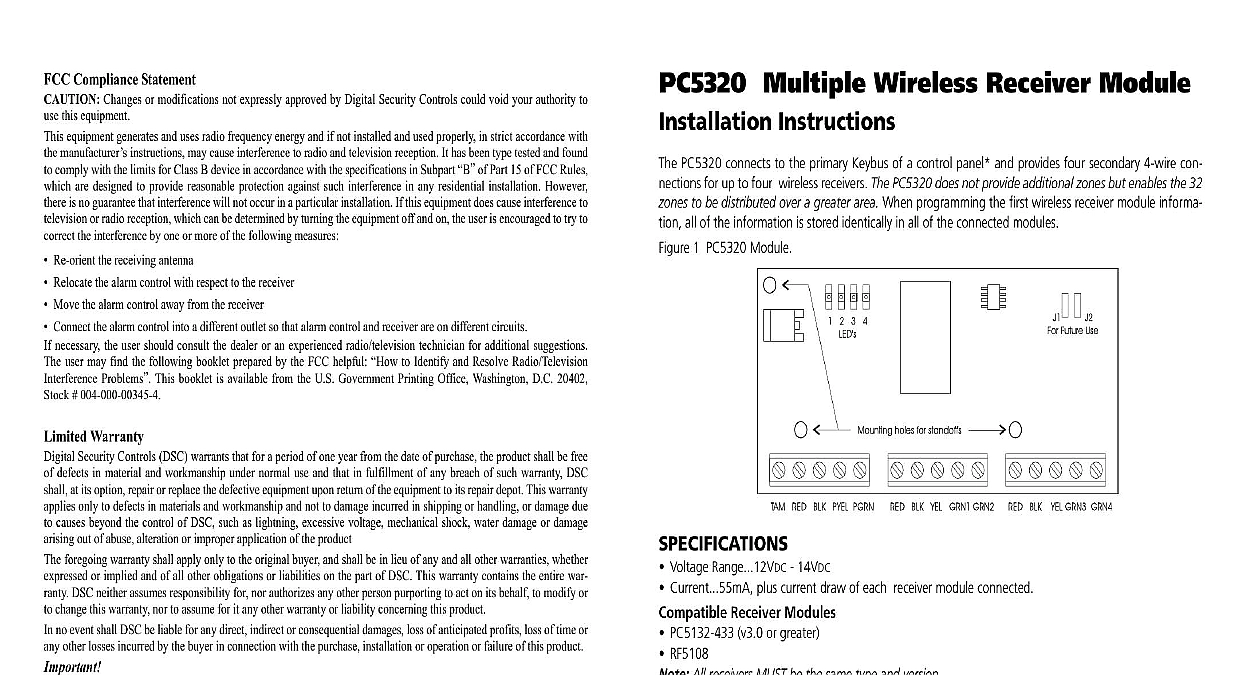
FCC Compliance Statement Changes or modifications not expressly approved by Digital Security Controls could void your authority to this equipment equipment generates and uses radio frequency energy and if not installed and used properly in strict accordance with manufacturer instructions may cause interference to radio and television reception It has been type tested and found comply with the limits for Class B device in accordance with the specifications in Subpart of Part 15 of FCC Rules are designed to provide reasonable protection against such interference in any residential installation However is no guarantee that interference will not occur in a particular installation If this equipment does cause interference to or radio reception which can be determined by turning the equipment off and on the user is encouraged to try to the interference by one or more of the following measures Re orient the receiving antenna Relocate the alarm control with respect to the receiver Move the alarm control away from the receiver Connect the alarm control into a different outlet so that alarm control and receiver are on different circuits necessary the user should consult the dealer or an experienced radio television technician for additional suggestions user may find the following booklet prepared by the FCC helpful to Identify and Resolve Radio Television Problems This booklet is available from the U S Government Printing Office Washington D C 20402 004 000 00345 4 Warranty Security Controls DSC warrants that for a period of one year from the date of purchase the product shall be free defects in material and workmanship under normal use and that in fulfillment of any breach of such warranty DSC at its option repair or replace the defective equipment upon return of the equipment to its repair depot This warranty only to defects in materials and workmanship and not to damage incurred in shipping or handling or damage due causes beyond the control of DSC such as lightning excessive voltage mechanical shock water damage or damage out of abuse alteration or improper application of the product foregoing warranty shall apply only to the original buyer and shall be in lieu of any and all other warranties whether or implied and of all other obligations or liabilities on the part of DSC This warranty contains the entire war DSC neither assumes responsibility for nor authorizes any other person purporting to act on its behalf to modify or change this warranty nor to assume for it any other warranty or liability concerning this product no event shall DSC be liable for any direct indirect or consequential damages loss of anticipated profits loss of time or other losses incurred by the buyer in connection with the purchase installation or operation or failure of this product recommends that the entire system be completely tested on a regular basis However despite frequent testing and to but not limited to criminal tampering or electrical disruption it is possible for this product to fail to perform as This equipment is fixed and shall be installed by Service Persons only service person is defined as a having the appropriate technical training and experience necessary to be aware of hazards to which person may be exposed in performing a task and of measures to minimize the risks to that person or persons It shall be installed and used within an environment that provides the pollution degree max over voltages category II in non hazardous indoor locations only manual shall be used in conjunction with the Installation Manual of the alarm control panel All the specified within that manual must be observed 2005 Digital Security Controls Canada cid 127 www dsc com Support 1 800 387 3630 Canada US 905 760 3036 in Canada Multiple Wireless Receiver Module Instructions PC5320 connects to the primary Keybus of a control panel and provides four secondary 4 wire con for up to four wireless receivers The PC5320 does not provide additional zones but enables the 32 to be distributed over a greater area When programming the first wireless receiver module informa all of the information is stored identically in all of the connected modules 1 PC5320 Module Voltage Range 12VDC 14VDC Current 55mA plus current draw of each receiver module connected Receiver Modules PC5132 433 v3.0 or greater RF5108 All receivers MUST be the same type and version Control Panels PC5008 PC5010 PC5015 PC5020 PC580 PC585 PC1555 MX PC1565 P 832 P 8 Field LEDs on the PC5320 indicate the status of the connected receiver modules The four LEDs on the PCB indicate the status of the connected receivers The LEDs will not turn on until at least one wire zone serial number has been programmed If the PC5320 module loses communication with the the corresponding LED will flash If there is a problem with the Keybus between the panel and the all LEDs will flash Supervision zones are supervised by all of the receivers connected A zone supervisory trouble will occur if a transmit supervisory signal is not received by any of the connected receivers during the programmed time period Tampers Violations and Restorals tampers violations and restorals are processed by the PC5320 When a receiver connected to the detects a tamper violation or restoral the PC5320 will send the information to the panel Tampers Troubles PC5320 tamper has a tamper input If the PC5320 has a tamper condition the panel will display Tamper If a receiver connected to the PC5320 has a tamper condition the panel will display Tamper The tamper trouble will not be restored until the tamper is restored on the PC5320 mod and all connected receivers to Figures 1,2 and control panel Installation Manual for wiring details Select a location a location that ensures that the maximum wire run distances do not exceed the guidelines indicated Figure 2 The PC5320 can be mounted in the existing control panel or a separate plastic housing refer the control panel Installation Manual Locate module so that service personnel will have easy access to LEDs for troubleshooting and diagnostics Remove System Power Install PC5320 Module the three standoffs provided into the cabinet Press firmly until standoffs click into place Align the mounting holes over the standoffs and press module firmly into place Route the secondary bus in accordance with local regulations Wiring Receivers the receivers to the secondary terminals of the PC5320 module as follows RED BLK and YEL are to all receivers Connect the GRN wire of each receiver to GRN1 GRN2 GRN3 and GRN4 as One receiver MUST be connected to GRN1 to ensure proper operation that the connections to the terminals are secure before applying power Enroll Zones to the receiver Installation Manual to enroll wireless devices Enroll each wireless device and then the zones and partitions as required The control panel sees the the PC5320 as a single receiver Programming is passed through the to all receivers so that they are all programmed identically Perform Module Placement Test module placement test is used to find a good location for the transmitter Perform multiple module tests before mounting a transmitter to ensure good placement refer to the receiver Installation for more information PC5320 will send the best test to the panel For example if one receivers indicates a test result one displays a test result then a test result will be displayed The control panel will not allow a module placement test on a zone if one or more receivers do not a serial number for a zone programmed The keypad will emit a steady error tone when the zone is entered This can happen if a receiver is added or replaced after the initial programming If a is added or replaced after initial programming all wireless data must be programmed again The can be downloaded or programmed using a keypad programming using a keypad the correct wireless information may appear on the display Re enter information by typing over the displayed information with the same information PC5132 Programming programming is not allowed if any of the receivers connected to the PC5320 are in supervisory i e missing from the Keybus If a receiver is removed from the PC5320 the PC5320 supervision be reset To reset PC5320 supervision turn ON option 1 in section 804 subsection 97 After supervision the PC5320 will automatically turn the option OFF 8 Installer Cod