DSC PC5320 v1 0 - Installation Manual - English - French - PowerSeries Multiple Receiver Module - Can be used with multiple frequencies

File Preview
Click below to download for free
Click below to download for free
File Data
| Name | dsc-pc5320-v1-0-installation-manual-english-french-powerseries-multiple-receiver-module-can-be-used-with-multiple-frequencies-5471239086.pdf |
|---|---|
| Type | |
| Size | 887.92 KB |
| Downloads |
Text Preview
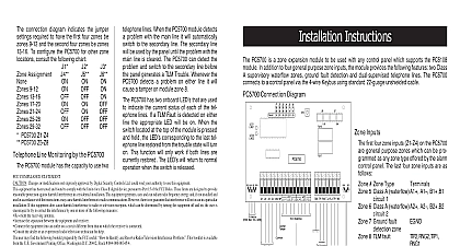
PC5320 Multiple Wireless Module Instructions PC5320 connects to the primary Keybus of a control panel and pro four secondary 4 wire connections for up to four wireless receivers 433 868 900 The PC5320 does not provide additional zones enables the 32 zones to be distributed over a greater area 1 PC5320 Module Remove System Power AC power battery and the Telecommunication Network from the Alarm Controller PC5320 Module the three standoffs provided into the cabinet Press firmly until click into place Align the module mounting holes over the and press module firmly into place Route the secondary bus in accordance with local regulations Wiring Receivers the receivers to the secondary terminals of the PC5320 module follows RED BLK and YEL are common to all receivers Connect the wire of each receiver to GRN1 GRN2 GRN3 and GRN4 as One receiver MUST be connected to GRN1 to ensure proper Ensure that the connections to the terminals are secure applying power Enroll Zones to the receiver Installation Manual to enroll wireless devices each wireless device and then program the zones and partitions required Receiver Programming control panel sees the PC5320 as a single receiver is passed through the PC5320 to all so that they are all programmed identically 8 Installer Code 804 97 1 PC5320 Enrolled Field Used Used Used Used Used Used Used If a wireless zone is violated when in Installer Programming the will show as violated when programming is exited After exiting ensure that the status of all wireless zones is correct If a zone indicates it is violated when it is actually secure the zone be violated then restored to confirm proper zone status 2 PC5320 Wiring Diagrams PC1616 PC1832 PC5015 PC5020 PC1555 MX PC1565 PC1864 PC5010 v2.0 RF5132 433 v5.0 RF5132 868 v5.0 Voltage Range 12VDC 14VDC Current 55mA plus current draw of each receiver module connected Receiver Modules Module shown or higher PC5132 433 v4.1 PC5132 900 v3.1 RF5108 Control Panels Module shown or higher PC580 PC585 Field LEDs on the PC5320 indicate the status of the connected receiver The four LEDs on the PC5320 PCB indicate the status of the con receivers The LEDs will not turn on until at least one wireless zone number has been programmed If the PC5320 module loses commu with the receiver the corresponding LED will flash If there is a with the Keybus between the panel and the PC5320 all LEDs will Supervision zones are supervised by all of the receivers connected A zone supervi trouble will occur if a transmitter supervisory signal is not received by of the connected receivers during the programmed time period Tampers Violations and Restorals tampers violations and restorals are processed by the PC5320 When receiver connected to the PC5320 detects a tamper violation or restoral PC5320 will send the information to the panel Tampers Troubles PC5320 tamper has a tamper input If the PC5320 has a tamper condi the panel will display Tamper If a receiver connected to the has a tamper condition the panel will display Tamper tamper trouble will not be restored until the tamper is restored on the module and all connected receivers to Figures 1 2 and control panel Installation Manual for wiring Select a location a location that ensures that the maximum wire run distances do exceed the guidelines indicated in Figure 2 The PC5320 can be in the existing control panel or a separate plastic housing to the control panel Installation Manual Locate module so that personnel will have easy access to the LEDs for troubleshooting diagnostics A Wire Coverage receivers the same B receivers different connecting different receiver types to the each receiver must be independently pro before connecting to the PC5320 The following can not be performed while are connected to the PC5320 Access codes 17 32 can NOT be programmed DLS can NOT be used to program the receivers DLS can NOT be used to program ANY access codes DLS can NOT perform a global download RF Jam will NOT function HHKs will NOT work Global Placement test can be used serial numbers of all wireless devices must be pro on each receiver regardless of device fre A 433MHZ device will result in a fault ONLY if the number is also programmed for that zone on a MHZ Receiver module placement test is used to find a good location for the Perform multiple module placement tests before mount a transmitter to ensure good placement refer to the receiver Manual for more information PC5320 will send the best test to the panel For example if one indicates a test result and one displays a test then a test result will be displayed The control panel will not allow a module placement test on a if one or more receivers do not have a serial number for a zone The keypad will emit a steady error tone when the zone is entered This can happen if a receiver is added or replaced the initial programming If a receiver is added or replaced after ini programming all wireless data must be programmed again The can be downloaded or programmed using a keypad programming using a keypad the correct wireless information appear on the display Re enter the information by typing over the information with the same information PC5132 Programming programming is not allowed if any of the receivers connected the PC5320 are in supervisory trouble i e missing from the Key If a receiver is removed from the PC5320 the PC5320 supervi must be reset To reset PC5320 supervision turn ON option 1 in 804 subsection 97 After resetting supervision the PC5320 automatically turn the option OFF 2a Connecting the PC5320 to the Panel total wiring for the PC5320 and receivers connected to the PC5320 not exceed 750ft 228.6m can connect to any Blk terminal Bus this configuration the wire distance each receiver can be up to 750ft from the PC5320 can connect to any Blk terminal Bus Perform Module Placement Test 2b Connecting the PC5320 to the Panel with a Separate Power Supply REPLACING ADDING ZONES Turn Power OFF Connect the receiver directly to the panel Turn Power ON Program the new device in the desired zone slot Perform placement test on the device steps a to c for each receiver on the system Turn Power OFF Connect the PC5320 to the panel and the receiv Turn Power ON Test all wireless zones i e tripped and restored to to the PC5320 correct operation step applies when using either Option A or B programming from This equipment is fixed and must be installed by Service Persons service person is defined as a person having the appropriate techni training and experience necessary to be aware of hazards to which person may be exposed in performing a task and of measures to the risks to that person or other persons It must be installed used within an environment that provides the pollution degree max over voltages category II in non hazardous indoor locations only manual shall be used in conjunction with the Installation Manual of alarm control panel All the instructions specified within that manual be observed Compliance Statement Changes or modifications not expressly approved by Digital Controls could void your authority to use this equipment equipment generates and uses radio frequency energy and if not installed and used in strict accordance with the manufacturer instructions may cause interference to and television reception It has been type tested and found to comply with the limits for B device in accordance with the specifications in Subpart of Part 15 of FCC which are designed to provide reasonable protection against such interference in any installation However t