DSC PC5400 v2 2 - Installation Manual - English - PowerSeries Printer Interface Module

File Preview
Click below to download for free
Click below to download for free
File Data
| Name | dsc-pc5400-v2-2-installation-manual-english-powerseries-printer-interface-module-1705286439.pdf |
|---|---|
| Type | |
| Size | 644.54 KB |
| Downloads |
Text Preview
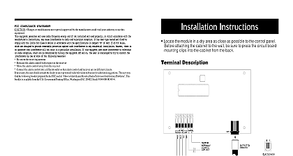
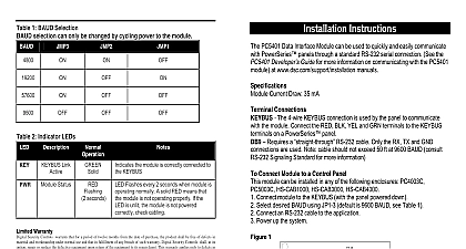
PC5400 Module v2.2TAFNZ INSTRUCTIONS compatible control panels to be connected a local serial printer Specifications 4 wire QUAD hook up to keybus Normal current draw of 35mA Tamper and Trouble reporting codes Maximum cable length 200 feet 61 meters connected to a serial printer True RS 232 technology DTR protocal Four baud rates 300 1200 2400 or 4800 Products PC5015 PC5010 PC5008 PC1580 PC1565 PC585 the Cabinet mounting a new cabinet for the PC5400 a dry location close to where the serial will be located mount the PC5400 Press the four white circuit board stand offs the raised mounting holes from the back the cabinet Hold the cabinet in position and pull the wires the cabinet Mount the cabinet securely to the wall using mounting screws provided Use the wall anchors when securing the to the drywall plaster concrete brick or similar surfaces With the cabinet mounted press the PC5400 into the stand offs to the Hook up Diagram included in this BLK YEL and GRN Terminals the RED BLK YEL and GRN terminals to RED BLK YEL and GRN terminals on the panel Refer to the control panel Manual for complete instructions on wiring and T2 T1 and T2 to a normally closed switch will be used to monitor tampers If no tamper is desired place a wire between T1 and T2 refer to the System Installation Manual for information on limitations regarding product and function and information on the limitations as to liability of the manufacturer W A R N I N G Hookup Diagram Programming you will be connecting the PC5400 to a PC5010 PC5008 PC1565 or PC585 control access the PC5400 programming sections a system keypad by entering 8 Installer s Then enter the 2 digit number of the you want to program you will be connecting the PC5400 to a PC1580 the PC5400 programming sections at a keypad by entering 8 Installer s Then enter the 2 digit number of the you want to program 01 Option 1 Printer Enable the module for use with a serial printer 01 Option 2 Handshake a handshake with the printer 01 Option 3 Printer the number of columns appropriate for printer Printer Configuration Language Selection Language 01 Options 4 to 7 Baud Rate the baud rate the PC5400 module will to communicate with the serial printer The rate is the speed at which information will be from the PC5400 module to the serial There are four different baud rates If you are experiencing problems with characters try lowering the baud rate 01 Option 8 Clock display how the clock displays the time 05 Printer Selection default language is English You can program module for French Spanish or Swedish If some characters do not print try changing the character set your uses ON Enabled from Printer DTR Column Printer Baud enabled Baud enabled Baud enabled Baud enabled clock displays 24hr time OFF Disabled Handshake Column Printer Baud disabled Baud disabled Baud disabled Baud disabled clock displays AM PM WARRANTY Security Controls Ltd warrants that for a period of twelve months from the date of purchase the product be free of defect in materials and workmanship under normal use and that in fulfilment of any breach of warranty Digital Security Controls Ltd shall at its option repair or replace the defective equipment upon of the equipment to its repair depot This warranty applies only to defects in parts and workmanship and to damage incurred in shipping or handling or damage due to causes beyond the control of Digital Security Ltd such as lightning excessive voltage mechanical shock water damage or damage arising out abuse alteration or improper application of the equipment foregoing warranty shall apply only to the original buyer and is and shall be in lieu of any and all other whether expressed or implied and of all other obligations or liabilities on the part of Digital Security Ltd This warranty contains the entire warranty Digital Security Controls Ltd neither assumes nor any other person purporting to act on its behalf to modify or to change this warranty nor to assume it any other warranty or liability concerning this product no event shall Digital Security Controls Ltd be liable for any direct indirect or consequential damages loss anticipated profits loss of time or any other losses incurred by the buyer in connection with the purchase or operation or failure of this product Digital Security Controls Ltd recommends that the entire system be completely tested on a basis However despite frequent testing and due to but not limited to criminal tampering or disruption it is possible for this product to fail to perform as expected COMPLIANCE STATEMENT C equipment generates and uses radio frequency energy and if not installed and used properly in strict accordance with the instructions may cause interference to radio and television reception It has been type tested and found to comply the limits for Class B device in accordance with the specifications in Subpart of Part 15 of FCC Rules which are to provide reasonable protection against such interference in any residential installation However there is no guarantee interference will not occur in a particular installation If this equipment does cause interference to television or radio which can be determined by turning the equipment off and on the user is encouraged to try to correct the interference one or more of the following measures 1998 Digital Security Controls Ltd Flint Road Downsview Ontario Canada M3J 2J6 665 8460 R0 in Canada