DSC PC5700 v1 0 - Installation Manual - English - PowerSeries Fire Module and Dual Phone Line Module

File Preview
Click below to download for free
Click below to download for free
File Data
| Name | dsc-pc5700-v1-0-installation-manual-english-powerseries-fire-module-and-dual-phone-line-module-6598304271.pdf |
|---|---|
| Type | |
| Size | 656.43 KB |
| Downloads |
Text Preview
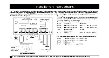
The connection diagram indicates the jumper required to have the first four zones be 9 12 and the second four zones be zones To configure the PC5700 for other zone consult the following chart Assignment 9 12 13 16 17 20 21 24 25 28 29 32 PC5700 Z1 Z4 PC5700 Z5 Z8 Line Monitoring by the PC5700 PC5700 module has the capacity to use two lines When the PC5700 module detects problem with the main line it will automatically to the secondary line The secondary line be used by the panel until the problem with the line is cleared The PC5700 can detect the and switch to the secondary line before panel generates a TLM Trouble Whenever the detects a problem on either line it will a tamper on module zone 8 PC5700 has two onboard LED that are used indicate the current status of each of the tel lines If a TLM Fault is detected on either the appropriate LED will be on When the located at the top of the module is pressed held the LED corresponding to the last tel line restored from the trouble state will turn This function will only work if both lines are restored The LED will return to normal when the switch is released COMPLIANCE STATEMENT Changes or modifications not expressly approved by Digital Security Controls Ltd could void your authority to use this equipment equipment has been tested and found to comply with the limits for a Class B digital device pursuant to Part 15 of the FCC Rules These limits are designed to provide protection against harmful interference in a residential installation This equipment generates uses and can radiate radio frequency energy and if not installed and in accordance with the instructions may cause harmful interference to radio communications However there is no guarantee that interference will not occur in a particular If this equipment does cause harmful interference to radio or television reception which can be determined by turning the equipment off and on the user is to try to correct the interference by one or more of the following measures Re orient the receiving antenna Increase the separation between the equipment and receiver Connect the equipment into an outlet on a circuit different from that to which the receiver is connected Consult the dealer or an experienced radio television technician for help user may find the following booklet prepared by the FCC useful to Identify and Resolve Radio Television Interference Problems This booklet is available the U S Government Printing Office Washington D C 20402 Stock 004 000 00345 4 INFORMATION equipment complies with Part 68 of the FCC Rules On the side of this equipment is a label that contains among other information the FCC registration number this equipment TO TELEPHONE COMPANY The customer shall notify the telephone company of the particular line to which the connection will be made and provide FCC registration number and the ringer equivalence of the protective circuit Registration Number F53CAN 32105 KX N Equivalence Number 0.1B Jack RJ31X CONNECTION REQUIREMENTS Except for the telephone company provided ringers all connections to the telephone network shall be made through plugs and telephone company provided jacks or equivalent in such a manner as to allow for easy immediate disconnection of the terminal equipment Standard shall be so arranged that if the plug connected thereto is withdrawn no interference to the operation of the equipment at the customer premises which remains to the telephone network shall occur by reason of such withdrawal OF HARM Should terminal equipment or protective circuitry cause harm to the telephone network the telephone company shall where practicable notify customer that temporary disconnection of service may be required however where prior notice is not practicable the telephone company may temporarily discontinue if such action is deemed reasonable in the circumstances In the case of such temporary discontinuance the telephone company shall promptly notify the customer will be given the opportunity to correct the situation TELEPHONE COMPANY INFORMATION The security control panel must be properly connected to the telephone line with a USOC RJ 31X jack FCC prohibits customer provided terminal equipment be connected to party lines or to be used in conjunction with coin telephone service Interconnect rules may from state to state IN TELEPHONE COMPANY EQUIPMENT OR FACILITIES The telephone company may make changes in its communications facilities equipment operations procedures where such actions are reasonably required and proper in its business Should any such changes render the customer terminal equipment incompatible with the telephone facilities the customer shall be given adequate notice to the effect modifications to maintain uninterrupted service EQUIVALENCE NUMBER REN The REN is useful to determine the quantity of devices that you may connect to your telephone line and still have all of those ring when your telephone number is called In most but not all areas the sum of the RENs of all devices connected to one line should not exceed five 5.0 To be of the number of devices that you may connect to your line you may want to contact your local telephone company MAINTENANCE FACILITY If you experience trouble with this telephone equipment please contact the facility indicated below for information on service or repairs The telephone company may ask that you disconnect this equipment from the network until the problem has been corrected or until you are that the equipment is not malfunctioning Security Controls Ltd 160 Washburn St Lockport NY 14094 Interface Code N A Order Code N A Instructions PC5700 is a zone expansion module to be used with any control panel which supports the PC5108 In addition to four general purpose zone inputs the module provides the following features two Class supervisory waterflow zones ground fault detection and dual supervised telephone lines The PC5700 to a control panel via the 4 wire Keybus using standard 22 guage unshielded cable Connection Diagram Inputs first four zone inputs Z1 Z4 on the PC5700 general purpose zones which can be pro as any zone type offered by the alarm panel The last four zone inputs are as Zone Type 5 Class A waterflow A1 A1 B1 B1 6 Class A waterflow A2 A2 B2 B2 1 2 7 Ground fault zone 8 TLM fault RNG2 TIP1 zone definitions for these four zones should as follows 5 07 Delayed Fire or 08 Standard Fire 6 07 Delayed Fire or 08 Standard Fire 7 08 Standard Fire 8 09 24Hr Supervisory LINKS J1 J6 are used to determine which zones will be assigned to the PC5700 Jumpers J1 J3 control the first four zones Jumpers J4 J6 control the second four PC5700 zones two water flow ground fault and TLM fault 1998 Digital Security Controls Ltd Flint Road Downsview Ontario Canada M3J 2J6 416 665 8460 Fax 416 665 7498 Tech Line 1 800 387 3630 in Canada 29002730 R1 Please refer to the System Installation Manual for on limitations regarding product use and function and on the limitations as to liability of the manufacturer Module


