DSC PC6400-Installation Sheet-PRINTER-English

File Preview
Click below to download for free
Click below to download for free
File Data
| Name | dsc-pc6400-installation-sheet-printer-english-5096812437.pdf |
|---|---|
| Type | |
| Size | 697.42 KB |
| Downloads |
Text Preview
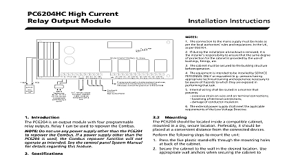
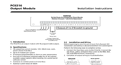
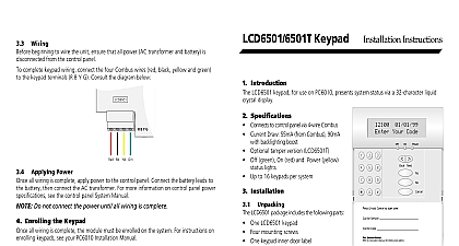
PC6400 Module Introduction PC6400 module adds serial printer support to a PC6010 system Specifications Four wire QUAD hook up to Combus Typical current draw of 35 mA Tamper and Trouble reporting codes Low Combus supervision to main control panel Maximum cable length 200 feet 61 meters True RS 232 technology Protocol DTR Baud rate 4800 Compatible cabinet PC4003C One module per system Installing the PC6400 Unpacking PC6400 package includes the following parts One PC6400 circuit board Four plastic stand offs Installation Instructions Mounting the Cabinet mounting a new cabinet for the PC6400 select a dry close to the serial printer mount the cabinet From the back of the cabinet press in the four white circuit stand offs into the raised mounting holes Holding the cabinet in position pull all wiring into the through the hole in the back Using the provided mounting screws and appropriate wall mount the cabinet securely to the wall Press the PC6400 module onto the plastic stand offs Wiring beginning to wire the unit ensure that all power AC and battery is disconnected from the control panel the following steps to complete wiring Connect the four Combus wires to the PC6400 Connect red black yellow and green Combus wires to the RED YEL and GRN terminals respectively Connect terminals T1 and T2 to a normally closed tamper If no tamper switch is desired connect a jumper between T1 and T2 terminals the following wiring diagram for further information Hookup Diagram refer to the System Installation Manual for information on limitations regarding product and function and information on the limitations as to liability of the manufacturer Programming the Module only programming sections relevant to the PC6400 are the PC6400 reporting codes To access PC6010 enter 8 followed by the Installer code control panel always watches for possible trouble If a trouble condition occurs a system fault will be on the keypad following trouble conditions apply to the PC6400 module a description of all troubles please see your System Combus Module Tamper Fault Combus Module Low Power programmed the panel can also send reporting codes for following conditions PC6400 Tamper Alarm PC6400 Tamper Restore RS 232 Trouble RS 232 Trouble Restore your reporting code choices in the panel Worksheets booklet Applying Power all wiring is completed apply power to the control panel the battery leads to the battery then connect the AC For more information on control panel power see the control panel System Manual Do not connect the power until all wiring is complete Enrolling the Module By default before you can enroll modules or change system programming a user must tell the system to System Service The system will then allow access to Programming for 60 minutes Any user with a code can tell the system to allow service at a system The default Master code is 1234 the Maintenance Manual for more information See Programming Manual Section for more on the Allows Serv toggle option all wiring is complete you must enroll the module Enter installer programming by pressing 8 Installer Scroll to Hardware and press the key Scroll to Module and press the key Scroll through the different modules until is Press the key The message Tamper on Desired Unit will be To create the required tamper secure the zone on the module and then open it The keypad display the module number and will confirm enrollment Mod 01 Enrolled more information regarding module enrollment see the panel System Manual Products Digital Security Controls Ltd Canada www dscgrp com in Canada 29004921 R001