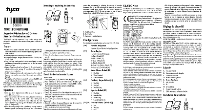
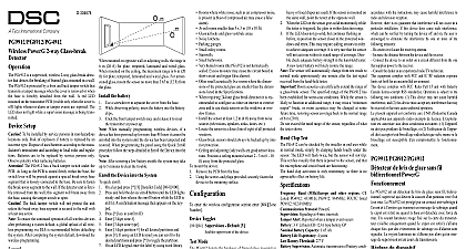
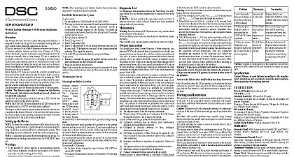
DSC PG9901-8901-4901 Installation Manual En-Fr-Sp-Po - 229010024R003

File Preview
Click below to download for free
Click below to download for free
File Data
| Name | dsc-pg9901-8901-4901-installation-manual-en-fr-sp-po-229010024r003-3627901485.pdf |
|---|---|
| Type | |
| Size | 1.96 MB |
| Downloads |
Text Preview
D 305868 Wireless PowerG Indoor Siren Instructions PGx901 is a fully supervised 2 way wireless PowerG indoor designed for installation in areas where wiring is difficult Built in link quality indicators reduce installation time by the need for the installer to physically approach control panel Multiple sound types Burglar between 1400Hz 3200Hz gas CO and flood Entry Exit beep can be enabled via the control panel to sound the user has armed the system and once the user has the protected area Squawk beep sounds can be configured via the control panel indicate alarm system arming 1 squawk and disarming 2 by a wireless key Double Tamper protection sends a tamper alarm to the system the siren front panel is removed or if the siren is removed the wall Sounder activates for a predefined duration as per local or until the system is disarmed The strobe light as described in the HSM2HOST installation manual Siren and strobe light activate when an identified event is received from the alarm system When the battery voltage is low a low battery message is sent the alarm system After message delivery at least 2 siren are possible before the siren is totally inactive Setup To be installed by service persons in non hazardous only Risk of explosion if battery is replaced by an type Observe polarity when installing batteries Dispose used batteries according to the manufacturer instructions and to local rules and regulations Batteries are to be replaced by service persons only To ensure the continued operation of all wireless devices performing a system default a global upload of all wireless via DLS is recommended before defaulting the sys After completing the system default download the wireless Battery connector Enroll button Self test button Dual battery cable adapter For back tamper screw or the Loosen cover screw and cover Using the cable connect to the proper When manually wireless if a device has powered up for more 48 hours it cannot be into the system the device has been and restored programming the using the Quick procedure follow steps detailed in the Device After restoring a low battery trouble the system may take to 5 minutes to clear the trouble the Device to the PowerSeries Neo Host Installation Manual or iotega Manual for the enrollment procedure Diagnostics and Placement Test permanently mounting any wireless device it is recom to mount the device temporarily and perform a Local test Before testing remove the plastic cover Press the self test button once and release it The red LED will ON and then OFF the green LED will switch ON and OFF the strobe light will switch ON and then OFF and piezo siren will sound to indicating that the siren is fully After 2 seconds the LED blinks 3 times indicating the signal communication following table indicates the received signal strength response LED blinks LED blinks LED blinks blinks Only GOOD or STRONG signal strengths are If you receive a POOR signal from the device re it and re test until a GOOD or STRONG signal is received For UL ULC installations only STRONG signal levels are After installation verify the product functionality in with the compatible receivers For detailed Placement instructions refer to the control Reference Guide the Device Mark for drilling Drill 4 holes Fasten with 4 supplied screws following programmable option is available Assignment the digits of desired assigned partitions Toggles following are 8 bit toggles Fire Default ON CO Default ON Burg Default ON Flood Default ON Auto Tmp Alarm Default OFF Alarm Default 01 Disabled Timer Limited Until Disarmed Entry Beeps Default 01 Disabled Enabled Disabled Stay Default 02 Disabled Sounder Only Strobe Only Sounder and Strobe Volume Default 02 Low Medium High Sound Level 85 dB at 3 m 10 feet Band MHz CE Listed PG4901 433MHz CE EN PG8901 868MHz FCC IC UL ULC PG9901 GFSK Built in antenna Protocol PowerG Type One Piezo 109 db min Sound Pressure Level 1m 3200 Hz sweep frequency 7 Hz Type Four 3.6V 3.5A H Lithium independent cells ER18505M assembled in two plastic wrappings and con to the cable adapter Use only the above battery The strobe flashes 5 times and the red LED lights continu during first battery installation Life Expectancy 8 years not verified by UL ULC Battery Threshold 2 V 300 mV negative slope OR 1.2 V Light Pulsed 1 sec range 10 to 55 UL ULC only verified the 0 Humidity up to max 93 RH non condensing UL only verified up to max 85 RH L x W x D 161x161x50 mm 6 7 16 x 6 7 16 x1 in including battery 470g 16.5 oz White with transparent lens Receivers device can be used with DSC panels and receivers that use technology UL ULC installations use these device only in conjunction compatible DSC wireless receivers WS900 19 WS900 29 HS2LCDRF P 9 HS2ICNRF P 9 and PG9920 installation verify the product functionality in conjunction the compatible receiver used Only devices operating in band 912 919MHz are UL ULC Notes PG9901 has been listed by UL ULC for Residential Burglary Fire applications in accordance to UL 1023 C1023 Household Alarms system units and UL 985 ULC S545 Household PG8901 is certified by DNV DET NORSKE to the following standards EN50131 4 GRADE 2 CLASS II EN50131 6 Type DNV DET NORSKE VERITAS has certified the 868 MHz variant of this product According to EN and A1 2009 this equipment can be applied in systems up to and including Security Grade 2 Environ Class II UK The PG8901 is suitable for use in systems to conform to PD6662 2010 at Grade 2 and environmen class 2 BS8243 The Power G peripheral devices have two communication functionality providing additional benefits described in the technical brochure This functionality has not tested to comply with the respective technical requirements should therefore be considered outside the scope of the prod certification COMPLIANCE STATEMENT Changes or modifications to this unit not expressly by the party responsible for compliance could void the authority to operate the equipment device has been tested and found to comply with the limits a Class B digital device pursuant to Part 15 of the FCC Rules limits are designed to provide reasonable protection against interference in residential installations This equipment uses and can radiate radio frequency energy and if not and used in accordance with the instructions may cause interference to radio and television reception However is no guarantee that interference will not occur in a particu installation If this device does cause such interference which be verified by turning the device off and on the user is to eliminate the interference by one or more of the measures Re orient or re locate the receiving antenna Increase the distance between the device and the receiver Connect the device to an outlet on a circuit different from the that supplies power to the receiver Consult the dealer or an experienced radio TV technician equipment complies with FCC and IC RF radiation exposure set forth for an uncontrolled environment To comply with FCC and IC RF exposure compli requirements the smoke detector should be located at a dis of at least 20 cm from all persons during normal operation antennas used for this product must not be co located or oper in conjunction with any other antenna or transmitter This complies with FCC Rules Part 15 and with Industry Can licence exempt RSS standard s Operation is subject to the two conditions 1 This device may not cause harmful and 2 this device must accept any interference that be received or th


