DSC PG9905-PG8905-PG4905 Installation Manual ENG FRE SPA POR - 29008705R001

File Preview
Click below to download for free
Click below to download for free
File Data
| Name | dsc-pg9905-pg8905-pg4905-installation-manual-eng-fre-spa-por-29008705r001-4169573082.pdf |
|---|---|
| Type | |
| Size | 2.53 MB |
| Downloads |
Text Preview
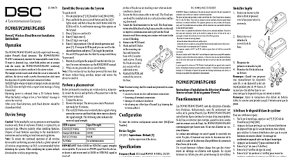
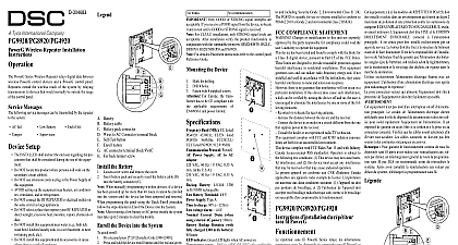
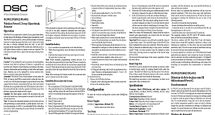
D 304679 Remove the screw separate the cover the base PowerG Temperature Detector Instructions PGx905 is a wireless PowerG detector for both indoor and out applications The detector monitors room temperature using internal sensor For outdoor or refrigerator installations a water temperature probe optional is used The PGx905 can be in instances where temperature detection is critical examples of detector usage are as follows Activating and deactivating pipe heaters at locations where temperatures may cause the water in pipes to freeze Warn of possible electrical device malfunction due to high low temperature levels Alerting elderly people of a significant rise or drop in room Internal temperature sensor An optional external temperature probe PGTEMP enables outdoor and refrigerator temperature sens Fully supervised PowerG detector Built in link quality indicators reduce installation time by the need for the installer to physically approach control panel Long battery life Low battery supervision Probe disconnected supervision Includes a anti collision transmission sequence that prevents collisions with transmitted mes from other PowerG devices series detectors update the alarm system control panel any change of temperature Based upon the configuration a chosen temperature point has been reached the control generates an alarm or warning message sends a notification the central station and if configured uses the PGM controls to on a connected appliance e g a heater or an air condi When the temperature returns across the configured thresh a restore message is generated using the temperature probe temperature measurements are performed by the probe sensor When the probe is not con and its terminals are shorted the temperature measurement performed only by the detector internal sensor further reliability the PGx905 tamper switch is activated when detector cover is removed Operating power is obtained from an 3 V Lithium battery A weak battery will result in a message When using the temperature probe to monitor refrigerator install the temperature probe inside the refrigerator install the detector on the wall or ceiling For outdoor installa install the temperature probe outdoors and install the detec indoors Setup To be installed by service persons in non hazardous loca only Risk of explosion if battery is replaced by an incorrect Observe polarity when installing batteries Dispose of used according to the manufacturer instructions and accord to local rules and regulations To ensure the continued operation of all wireless devices performing a system default a global upload of all wireless via DLS is recommended before defaulting the sys After completing the system default download the wireless Transmission LED Terminal block for sensor Enroll button Tamper switch the battery Temperature sensor Mounting holes Break away tamper a flat edged screw into the slot and push to remove cover Observe polarity and battery Connect the sensor wire to the ter block Optional When manually programming devices if a device has been up for more than 48 hours it be enrolled into the system the device has been tampered and When programming the panel the Quick Enroll procedure fol the steps detailed in Enroll the Device into the System After restoring a low battery trouble the system may take up 5 minutes to clear the trouble the Device into the System quick enroll On a keypad press 8 Installer Code 804 000 and hold the device enroll button until the LED lights and then release the enroll button while the LED is still A confirmation message then appears on the keypad key to confirm ID 3 digit zone 3 digit zone type 1 digit partition for all desired partitions and press If using an LCD keypad you can scroll to the desired par and press to toggle the partition On an LCD keypad enter the label by using word library pre enroll Remotely configure the unique ID number into the system more information see the HSM2HOST manual When on site press the device enroll button If the wireless device has been powered for more than 48 without being enrolled tamper and restore the device to it a placement test permanently mounting any wireless device temporarily the device and perform a Placement test the device by removing the cover Restore the tamper and the red LED blinks once to identify a signal is being sent to the receiver and then blinks three to identify the signal strength To perform further tests and restore the device The following table indicates received signal strength Strength communication response LED blinks LED blinks LED blinks blinks Only GOOD or STRONG signal strengths are If you receive a POOR signal from the device re locate and re test until a GOOD or STRONG signal is received For UL ULC installations only STRONG signal levels are After installation verify the product functionality in with the compatible receivers HSM2HOST9 HS2LC HS2ICNRF P 9 and PG9920 For detailed Placement instructions refer to the control panel Guide PGx905 can be installed indoors on walls or ceilings and in direction When installing outdoors or on refrigerators use the probe the backplate in the monitored area as close as possible to control panel to ensure optimum reception of the RF signal Open probe terminals generate a Disconnected Trou transmission the battery between the battery clips at the correct polarity proper operation only a Lithium battery type CR123A be used When replacing a battery it is necessary to wait 30 seconds removing the old battery and inserting the new one Adhesive tape not to be used for EU Market catch and remove Mark and drill 2 holes in mounting surface Fas base with 2 counter screws Reinsert PCB into base and connect the two wires of the probe the terminal block enter the wireless configuration section enter 804 3 digit zone Toggles Alarm LED Default Y the devices LED to activate when an alarm occurs Supervision Default Y supervision of the device For the temperature alarm to operate the temperature warn must either be disabled 999 or configured as the first tempera threshold High Temp Warn Default 999 Press for a temperature warning threshold If the thresh is passed all keypad buzzers sound steady in degrees High Temp Alarm Default 999 Press for a temperature alarm threshold If the threshold passed all bells sirens sound in degrees Low Temp Warn Default 999 Press for a temperature warning threshold If the thresh is passed all keypad buzzers sound steady in degrees Low Temp Alarm Default 999 Press for a temperature alarm threshold If the threshold passed all bells sirens sound in degrees Band MHz Europe and rest of world CE Listed 433MHz CE listed PG8905 868MHz FCC IC UL ULC PG9905 912 919MHz Protocol PowerG protection 20 V m 80 to 2000 MHz measurement accuracy internal sensor or probe cable length 3.5m type 3 V Lithium battery CR123A Panasonic Sanyo or only consumer grade Life Expectancy 7 years not verified by UL ULC Battery Threshold 2.2 V Supervision Automatic transmission of battery condi data as part of any status report Temperature indoor 20 to 50 4 to 122 Operating Temperature outdoor 30 to 70 22 158 Temperature indoor 20 to 60 4 to 140 LxWxD 92 x 36.5 x 31 mm 3 5 8 x 1 7 16 x 1 1 4 excluding battery 50 g 1.8 oz Receivers Band HSM2HOST4 HS2LCDRF P 4 HS2IC PG4920 Band HSM2HOST8 HS2LCDRF P 8 HS2IC PG8920 Band HSM2HOST9 HS