DSC PG9914 8914 4914 - Installation Guide - EN FR ES PT

File Preview
Click below to download for free
Click below to download for free
File Data
| Name | dsc-pg9914-8914-4914-installation-guide-en-fr-es-pt-7386915402.pdf |
|---|---|
| Type | |
| Size | 3.40 MB |
| Downloads |
Text Preview
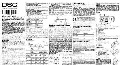
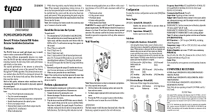
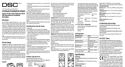
PG9914 PG8914 PG4914 Wireless PIR Pet Immune Motion Detector Installation PGx914 pet immune is a microprocessor controlled wireless digital PIR supported by DSC alarm systems using PowerG two way protocol Do not pull the battery tab until after you enroll the device Enroll the by scanning the QR code that is on the device or follow the for enrolling the device to the panel detector features are as follows and cylindrical lenses with uniform detection sensitivity its operating range up to 12 meters 39 ft Specific Imaging TSI technology is used for distinction humans and pets weighing up to 38 kg 85lb advanced True Motion Recognition algorithm patented between the true motion of an intruder and any other which may cause false alarms No vertical adjustment is needed Motion event counter determines whether 1 or 2 consecutive motion trigger an alarm low current consumption Microprocessor controlled temperature compensation Sealed black provides white light protection and back tamper protection device supports temperature and light level reports to compatible systems that support temperature and light sensors UL installations The detector is for use with UL listed control units only immunity has not been evaluated by UL Enroll button Light sensor LEDs Tamper switch PIR sensor View Installation guidance Keep away from heat Do not expose to air Do not install outdoors Avoid direct sunshine Do not install near high electrical lines Do not install behind Mount on a solid stable Do not partially or completely obscure the detector field of view Procedure Surface mount Corner mount B1 or B2 Back tamper PGx914 Installation Instructions Cover Base Press in point The detector transmits a low battery signal upon detection of low It is recommended to wait about 1 minute after battery removal inserting the new battery shall be installed in accordance with the Standard for Installation and of Burglar and Holdup Alarm Systems UL 681 When using the corner mounting bracket only use the holes on one of the bracket do not use the holes on both sides of the bracket Risk of explosion if battery is replaced by an incorrect type Dispose used battery according to the manufacturer instructions the Pet Mask the plastic pet mask if you do not require pet immunity Place your thumb at the base of the Pet Mask Place your fingers at the top of the Pet Mask Lift the Pet Mask to remove from Bracket the alarm systems Installation Guide and follow the enrollment general description of the procedure is provided in the following flow chart Procedure the Installation Manual for the alarm system that the device is enrolled on to ensure that the proper steps are used the Device Enrollment option through the specified method select the appropriate option to add a new device the enrollment tab or insert the battery to power on the device begin the auto enrollment process If the device does not automatically enroll enter ID xxx xxxx number of the device that is printed on the label or press the button on the device to begin the enrollment process the desired Zone Number any device parameters that are required and test the detector See section 3 for information on testing device In addition see the alarm systems Installation Manual the device is enrolled on for other test procedures that are the detector is already enrolled you can configure the detector parameters programming the system see the alarm systems Installation Manual for information about device parameters Display instructions on displaying the temperature of zones on the control panel measured by PGx914 detectors see the alarm systems Installation Manual details Configuring the Detector Parameters the DEVICE SETTINGS menu and follow the configuration instructions the PGx914 detector as described in the following table Instructions whether or not the alarm LED indication will be activated settings LED ON default and LED OFF whether an alarm will be activated upon continued low sensitivity or upon a single alarm event high Optional settings LOW sensitivity default and HIGH whether or not the sensor is active when the system is Optional settings NOT Active while disarmed no delay 5s delay 15s delay 30s delay 1m delay delay 5m delay 10m delay 20m delay and 60m delay LOCAL DIAGNOSTICS TEST Run a diagnostic test at least once a week to ensure that the detector working correctly the base from the cover the cover to return the tamper switch to its normal position and then secure the front cover to the base with case closure screw PGx914 detector will enter a 2 min stability period During this time red LED blinks Walk test the coverage area Walk across the far end of the coverage in both directions The red LED lights each time your motion is followed by 3 LED Instruct the user to walk test at least once a week to verify functioning of the detector Mount the bracket on the wall in the point marked F in the drawing and the cover from the base the battery while observing polarity OR If battery already installed remove the activation strip that from the back of the detector the cover to the base until a click is heard the is closed the detector with the screw the detector with the bracket the detector upward until a click is heard Release screw Separate the cover from the base Remove battery Press on the stopper snap to release the base from the bracket Slide the base downward to remove following table outlines received signal strength indication response LED blinks Strong LED blinks Good LED blinks blinks communication strip3firealarmresources com alarm system must not be regarded as a substitute for insurance owners or renters should be prudent to continue insuring their even though they are protected by an alarm system Type element low noise pyroelectric Reliable reception must be assured Therefore poor signal is not acceptable If you receive a poor signal from the device re it and re test until a good or strong signal strength is received UL ULC installations only STRONG signal level are acceptable installation verify the product functionality with the compatible receivers HS2LCDRF P 9 HS2ICNRF P 9 PG9920 and WS900 29 For detailed placement instructions see the alarm systems Installation sensor and the panel do not TROUBLESHOOTING you encounter one of the following problems with the PGx914 perform suggested solution from the following table to enroll the sensor is that the detector is within communication range of the Ensure that the enroll on the device is held until the flash is seen and then a placement test as in the alarm systems Manual Ensure that the is within wireless range of the receiver remove any possible sources of If necessary replace sensor battery ensure continuous proper replace the battery within weeks of the first low battery the diagnostic test procedure Section 3 above to test the Replace the battery if LEDs are not seen during test If the system still cannot be consult with your alarm technician for a solution does not arm because of a malfunction sensor sends a low battery COMPLIANCE WITH STANDARDS PG8914 model complies with the following standards EN 300220 EN 301489 EN 60950 1 EN 50130 4 50131 1 EN 50131 2 2 Grade 2 Class II EN 50130 5 EN Type C The PG8914 model is suitable for use in systems installed conform to PD6662 2010 at Grade 2 and environmental II DD243 and BS8243 Certified by Applica Test AS in accordance with EN 50131 2 2 EN 50131 EN 50131 6 EN 50130 4 EN 50130 5 T C has certified only the 868 MHz variant of this EU DECLARATION OF CONFORMITY Tyco Safety Products Canada Ltd declares that this equipment is in compliance with Directive 2014 53 EU full text of the EU declaration of conformity is available the models mentioned below are available at the Internet addresses www dsc com pdf 1707